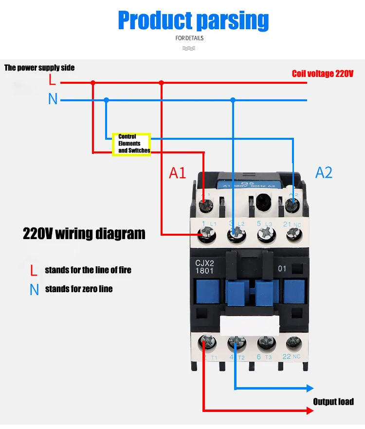
A wiring diagram is a simplified traditional photographic depiction of an electrical circuit. A wiring diagram is a streamlined conventional photographic representation of an electric circuit.
25f5f19 Mg Tc Wiring Diagram Wiring Resources
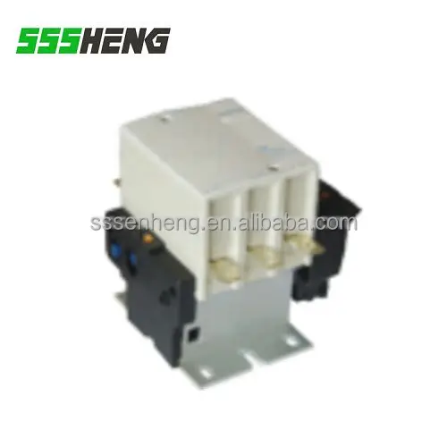
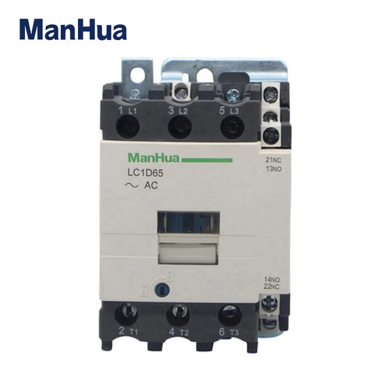
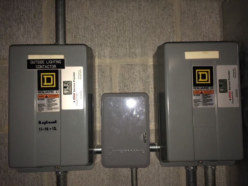
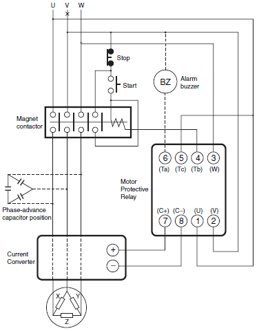
Tc contactor wiring diagram. It reveals the components of the circuit as streamlined forms and the power and signal links in between the tools. Tc electric delivers a comprehensive range of electrical equipment to our customers and is committed to delivering the highest quality product solutions in the industry. Collection of ac contactor wiring diagram. Connect rtd1 rtd2 of a b rtd 6 7 8 910 2 for rtd pt 100 2 wire 3 wire 3 wire pt100 to terminal no. Utilizing our global engineering design and support. Connect pt100 between terminal no.
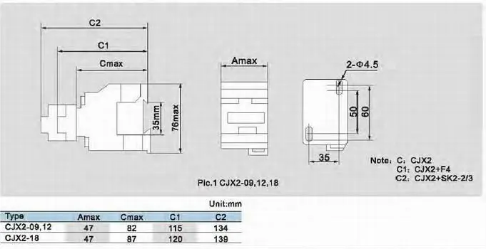
It shows the components of the circuit as streamlined shapes and the power and signal connections in between the tools. 1 for thermocouple tctc 6 7 8 910 thermocouple 1 for two wire pt 100. Variety of 2 pole contactor wiring diagram. 2 days ago i wired 380 to 440 volts contactor for a 3 phase motor and save these images of contactor in pc. 7 8 and rtd3 to terminal no. Short terminals 8 9.
Its is important to. 7 8 2 for three wire pt 100. Collection of contactor wiring diagram pdf. Contactor wiring and i hope after this post you will be able to wire a 3 phase motor i also published a post about 3 phase motor wiring with magnetic contactor and thermal overload relay but today post and contactor wiring diagram is too simple and easy to learn. Iec contactors overloads. A wiring diagram is a simplified traditional pictorial representation of an electrical circuit.
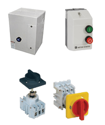
Motor controllers starters. It reveals the elements of the circuit as streamlined forms and the power and also signal links between the gadgets. Control signaling.
Gallery of Tc Contactor Wiring Diagram