The spd performance can be gauged by the information provided by the supplier. Spd surge protection device a transient over voltage protection device acts as a voltage controlled switch and is installed between the active conductors and ground in parallel.
Surge Protection Surge Suppressors Eaton
Surge protection device wiring diagram. A wiring diagram is a simplified traditional photographic representation of an electrical circuit. Collection of 3 phase surge protector wiring diagram. A wiring diagram is a streamlined traditional pictorial depiction of an electrical circuit. Make sure to grommet the hole in the distribution box. Midnite solar surge protection device spd midnite solar inc. Class 1 and class 2 protection for 380vac.
The important parameters when selecting a surge protection device are. Protector in front of surges. Surge protector wiring diagram. Assortment of surge protector wiring diagram. Midnite solar inc. It shows the components of the circuit as simplified shapes and also the power and also signal links between the devices.
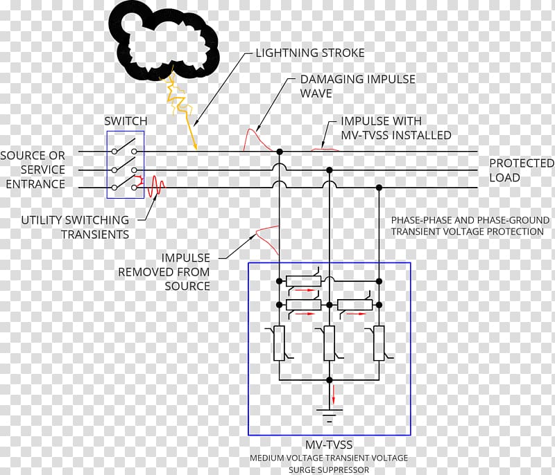
The performance of a surge protection device spd is governed by two main factors. See the diagram to the right from iec 63205 1 standard which displays the dispersion of the highest lightning considered. In order to limit overvoltages as much as possible a surge protection device must always be installed close to the equipment to be protected 3. Box after wiring is completed using drywall anchors. Single phase electricity explained wiring diagram energy meter duration. It reveals the components of the circuit as simplified shapes and the power as well as signal connections in between the tools.
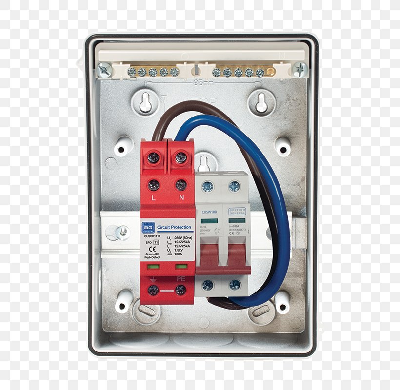
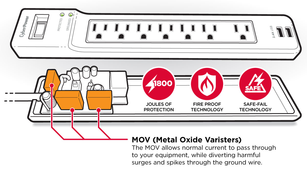
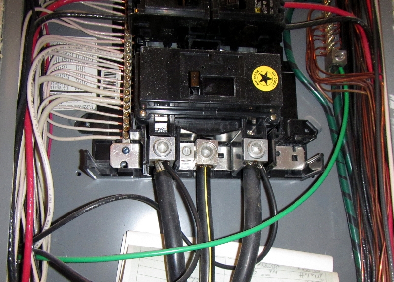
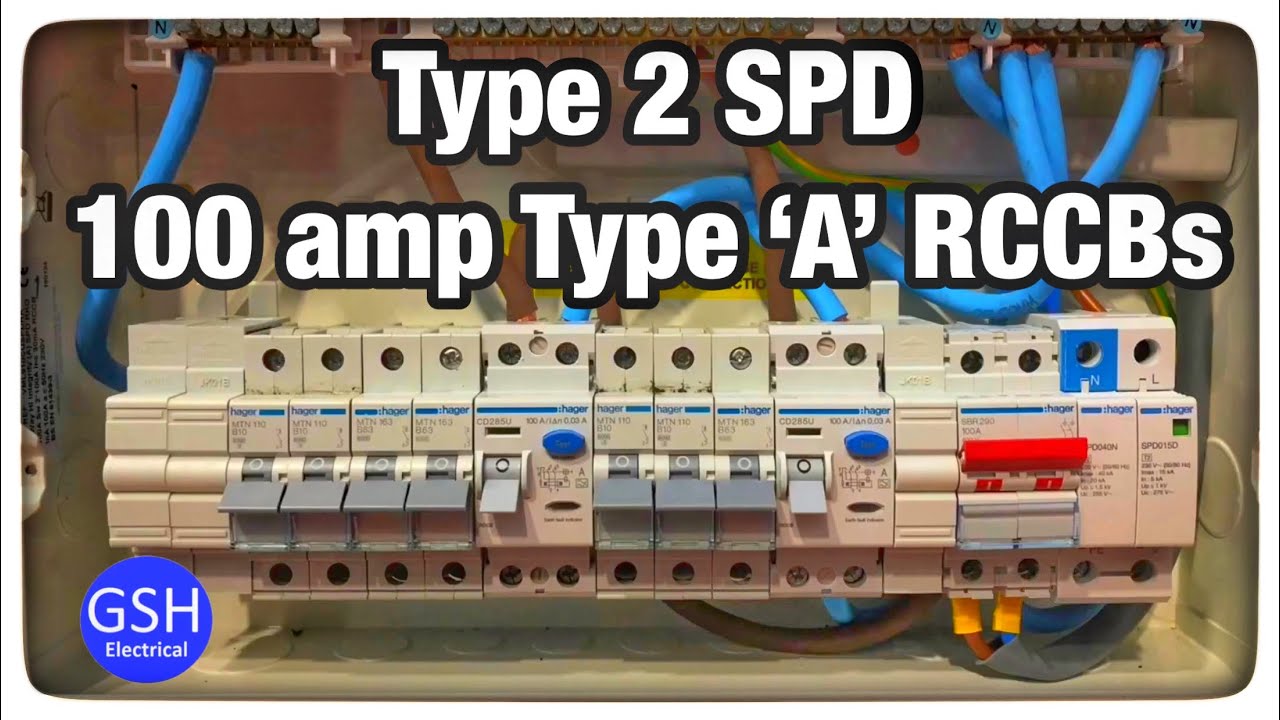
It is also important that the electrical distribution system be grounded and bonded per the national electrical code. The inclusion of surge protection devices spds in the 17th edition of the bs en 7671 wiring regulations amendment 1 shows how far the complexity and concern for personal safety of modern. Correct installation of hard wired surge protective device. 200ka at 10. A wiring diagram generally provides info about the relative placement as well as arrangement of tools and terminals on the devices to aid in structure or servicing the tool. The designed performance of the spd and the installation practices used on site.
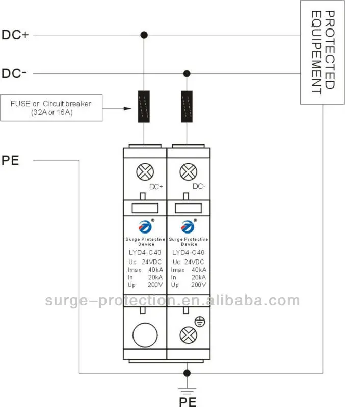
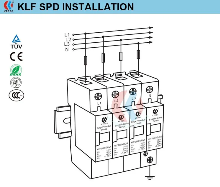
It is very important to follow the manufacturers installation instructions. Wiring diagrams for surge arresters wiring of 1 and of 3 x dehnguard 275 and 1 x dehngap ct. Warrants to the original customer that the spd products shall be free from defects in materials and workmanship for a period of five 5. Installation of class 1 and class 2 for 3 phase. Pay particular attention to fuse or breaker requirements and lead lengths. Installation of class 1 and class 2 for 3 phase.
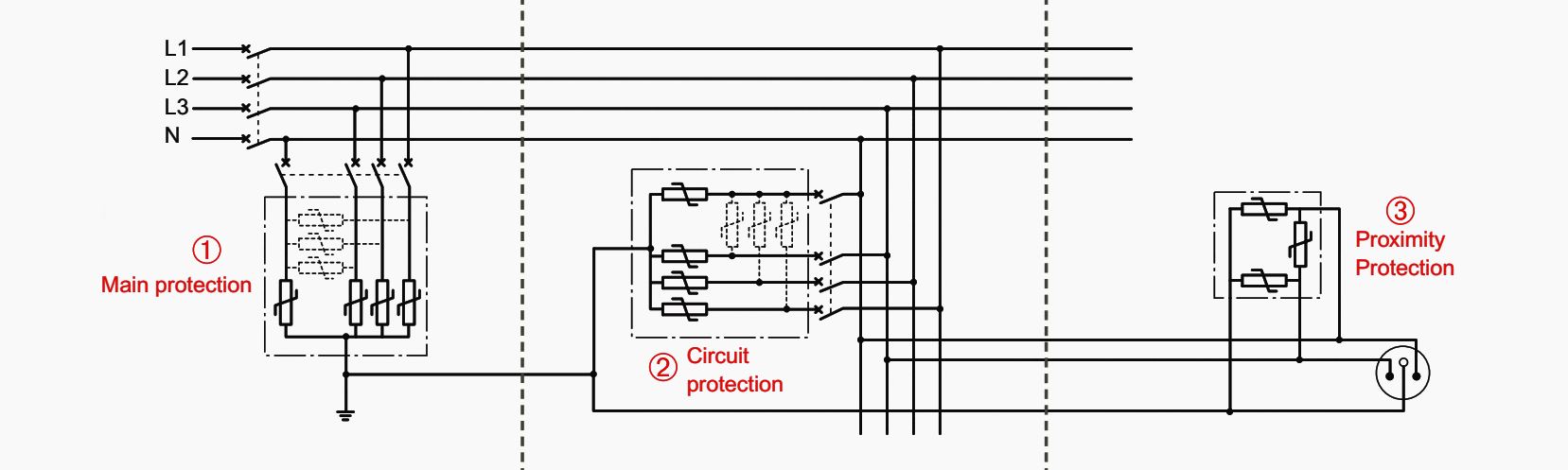
The terminal protection is close to the equipment provided using proximity surge protection devices. Installation of class 1 and class 2 single phase. A detailed look into the functionality of surge protection devices duration. Go back to content table 121 combination of several surge protection devices. To be clear spds do not protect an installation from lightning strikes only a fitted lightning.
Gallery of Surge Protection Device Wiring Diagram