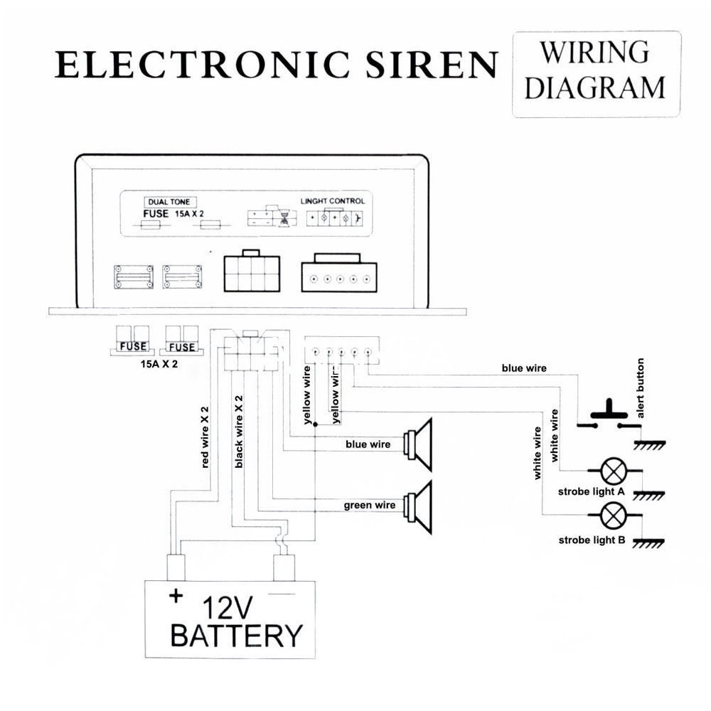
A wiring diagram is a simplified traditional photographic representation of an electrical circuit. The strobe light power supply should acquire its power from a low impedance source such as the alternator or generator end of the electrical buss.

D5a904 Meyers Light Kit Wiring Diagram Wiring Library
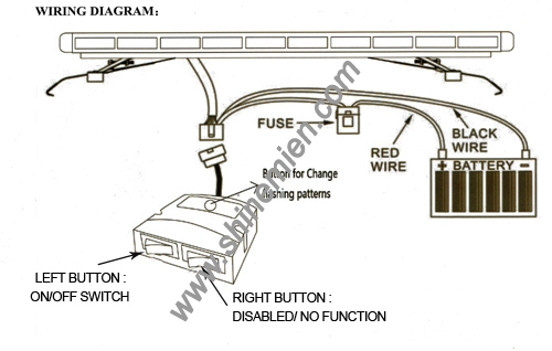
Strobe light wiring diagram. It shows the components of the circuit as simplified shapes and the power as well as signal connections between the devices. This latter point cannot be stressed enough. This power supply will operate up to 3 strobe light head assemblies. Equipment this product contains either strobe lights halogen lights high intensity leds or a combination of these lights. Historically the rotating beacon or strobe light circuit breaker is added on the electrical buss at the opposite end with the radio in between the strobe breaker and the low impedance end of the. Install guides page is being worked on.
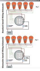
The pot remote input connector the bodies of all or any switch and all exposed metalwork including the strobe reflector must be connected to safety earth via a 3 core mains cable. Assortment of strobe light wiring diagram. It reveals the components of the circuit as streamlined shapes as well as the power as well as signal links in between the gadgets. In this video we demonstrate how to wire led emergency strobes to momentary switch. A wiring diagram is a streamlined standard photographic depiction of an electrical circuit. Assortment of 3 wire strobe light wiring diagram.
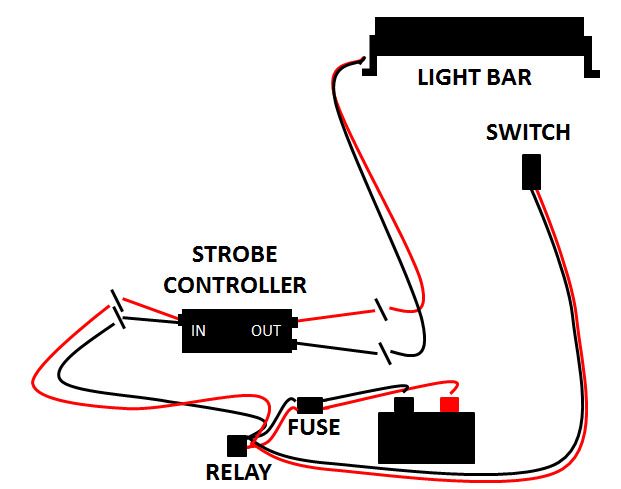
The strobe circuit is dangerous and the internal wiring can kill you on contact. Strobe light power supplies are. For permanent installations be sure to solder your wires or use weatherproof connectors. Shop our strobes.
Gallery of Strobe Light Wiring Diagram