Place the relays rated coil voltage on these terminals. 5x 12 volt 3040a spdt relay wire socket car automotive alarm 40 amp us seller see more like this.

Download Rib 2401d Dpdt Relay Wiring Diagram
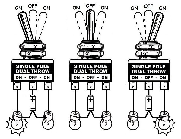
Spdt wiring diagram. Literally a circuit is the path that enables power to circulation. The objective is the same. With slide switches the switching movement is in a linear to and fro fashion. Pole refers to the number of circuits controlled by the switch. Single pole sp double pole dp switch wiring diagrams. A wiring diagram is a simplified traditional pictorial depiction of an electrical circuit.
Terminal 2 is the terminal which receives the power necessary so that the loads. What do spst spdt dpst and dpdt mean. I recently ran into a wiring problem and made an illustrated post on how i figured out the solution and some guesses as to why i came to the solution i did. Below is the schematic diagram of the wiring for connecting a spdt toggle switch. Hallway and corridor wiring circuit diagram using two way switches basically this circuit is same like staircase wiring circuit using two way spdt switches used to control the lighting circuit in a hallway and corridors. A spdt toggle switch has 3 terminals.
Terminal 1 can connect up to any load to power a certain device. Sp and dp refer to single pole and double pole st and dt refer to single throw and double throw. It reveals the parts of the circuit as streamlined forms and the power as well as signal links between the devices. It shows the elements of the circuit as simplified shapes and also the power and also signal connections between the tools. Hopefully it could save some people the hassle of having to rewire their project. Sp switches control only one electrical circuit.
The next diagram figure 3 shows the relay with the coil energized. Variety of 12 volt solenoid wiring diagram. The diagram below figure 2 shows an spdt relay at rest with the coil not energized. In corridor wiring circuit a lighting point is controlled from two different locations using 2 way switches. Spdt toggle switch wiring diagram a newbie s guide to circuit diagrams a very first appearance at a circuit diagram could be complex yet if you could check out a train map you could review schematics. The real benefit behind a relay is more than automation.
And terminal 3 can connect to any load to power any device. One of the most common pieces of circuit bending hardware is the single position dual throw spdt switch. Dp switches control two independent circuits and act like two identical switches that are mechanically linked. The switch only controls the relay. Spdt on on functions like two separate spdt switches operated by the same actuator. The 2 coil terminals is where the voltage is placed in order to energize the coil.
Below is the schematic diagram of the wiring for connecting a spdt toggle switch. Getting from factor a to direct b. Single pole double throw spdt relay wiring diagram this is the diagram below to learn all the pin terminals of a single pole double throw spdt relay. As you can see the coil is an electromagnet that causes the arm that is always connected to the common 30 to pivot when energized whereby contact is broken from the normally closed terminal 87a and made with the normally open terminal 87. Variety of spdt rocker switch wiring diagram.
Gallery of Spdt Wiring Diagram