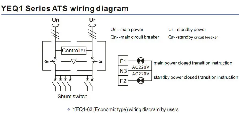
Manual mode is used for control the ats manually and to start stopping the generator engine. Wiring and if ok power up the product.

Control Wiring Diagram Ats
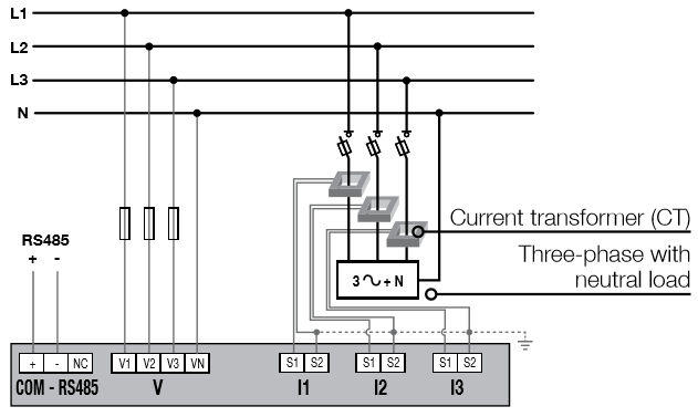
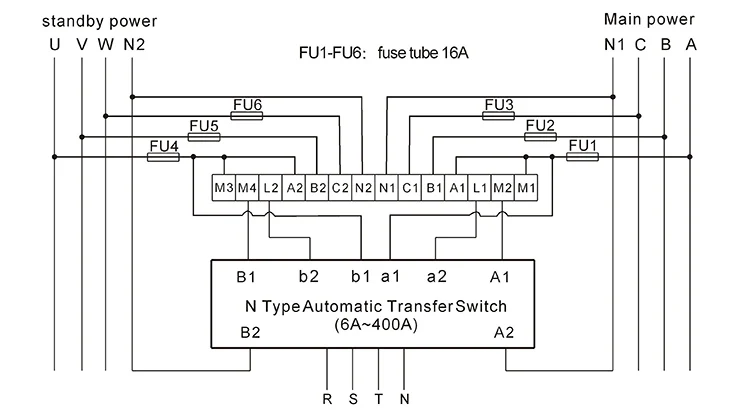
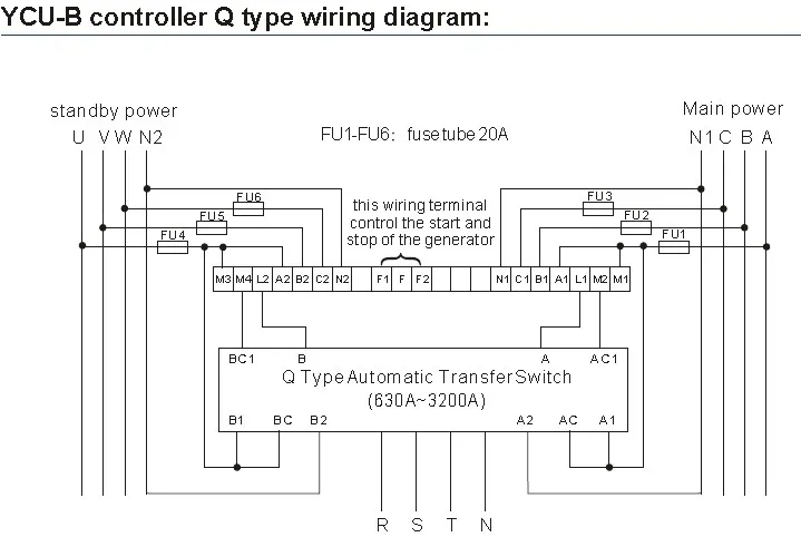
Socomec ats control wiring diagram. Type of control. Control connections a complete information package is furnished with each transfer switch including a complete connection diagram and schematic which details all necessary control circuit field connections. Typical automatic transfer switch diagrams technical information. Use of a socomec dps unit double power supply or of an independent power supply will allow control of the product in any of the three positions as soon as power is available on the product power inputs. Auxiliary free contact interface. Typical automatic transfer switch diagrams technical information.
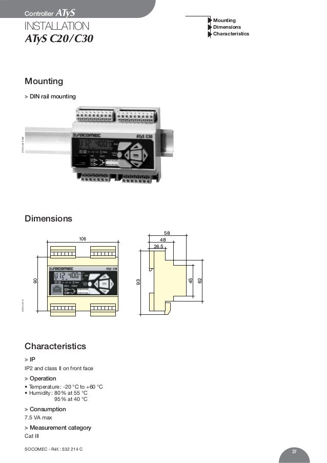
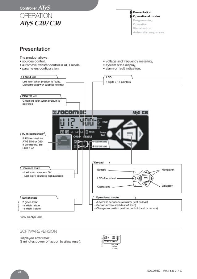
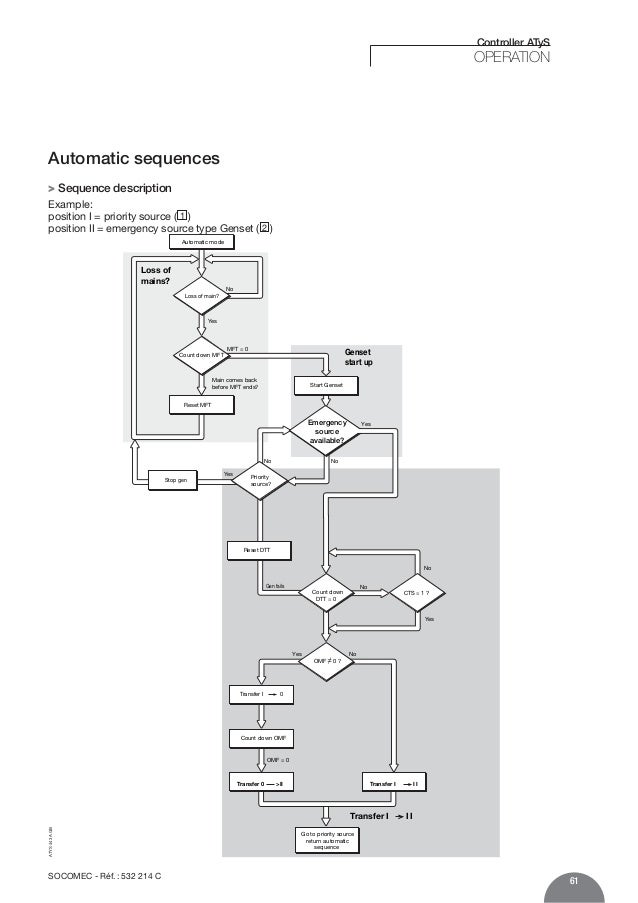
15 schematic circuit diagram for automatic transfer switch 16 recommended cable size 17 specifications. Ats control atys c30 atys r d10 atys r 4 d20 atys r 4f atys c30 atys r d20 atys r 4f rtse en 3. Full range of manual remotely operated and automatic transfer switches from 16 to 6300 amps. Control position i 2. The ats is connected to utility mains source the ats is connected to utility mains source 1 and the generator source 2 with utility mains as the preferred source. It shows the components of the circuit as simplified shapes and the capability and signal friends between the devices.
Socomec atys 3s wiring diagram transfer switching technology by socomec atys 125 3200a youtube socomec atys 3s wiring diagram wiring diagram is a simplified okay pictorial representation of an electrical circuit. The 0 position is in this type off control scheme only a transitory position. Power busbar and control wiring are color coded. The engine start control wires connect to the terminals specified in the upper left corner of the control panel. Q at hmsdm at mbd nm sgd oqnctbs at mc at mx nsgdq at rrnbh at sdc dptholdms hmbktchmf ats mns khlhsdc sn rdquhbhmf nodq at shnmr ltrs ad odqenqldc ax at cdpt at sdkx sq at hmdc at mc pt at khjdc odqrnmmdk q at bg oqnctbs hr rghoodc vhsg at k at adk nq nsgdq enql ne l at qjhmf hmbktchmf q at shmf at mc nsgdq hlonqs at ms rodbhjb oqnctbs hmenql at shnm. They are designed to isolate ats type electrical equipment automatic transfer switch or ups with minimum interruption to the load supply.
A wiring diagram is a simplified conventional photographic depiction of an electric circuit. Ats socomec solution operating table s1 s2 std socomec load 0 0 x x off 0 1 p2 q2 on 1 0 p1 q1 on 1 1 on. Sircover ats bypass switches are manual 12 4 pole transfer switches with positive break indication. 2 technical information standard ats diagrams. Providing an unrivalled benchmark in source switching socomec is continuously innovating to ensure ever more efficient ways to guarantee the continuity of distribution and therefore the rate of availability of your energy. The atys family product range.
Gallery of Socomec Ats Control Wiring Diagram