Plug the siga mct2 into any available position on the motherboard and secure the module to the motherboard with the captive screws. Siga ct1 wiring diagram architectural wiring diagrams reveal the approximate places as well as affiliations of receptacles lights as well as long term electrical solutions in a structure.

1957 Ford Wiring Diagram Wiring Diagram
Siga ct1 wiring diagram. Mount the uio motherboard inside a suitable est enclosure with screws and washers provided. The fire alarm control panel provides this function. Verify that all field wiring is free of opens shorts and ground faults. A wiring diagram is a streamlined standard pictorial representation of an electrical circuit. Mount the uio motherboard inside a suitable edwards enclosure with screws and washers provided. Wiring connections are made to the terminals on the motherboard see wiring diagram.
Collection of siga ct1 wiring diagram. It shows the elements of the circuit as simplified shapes and also the power and also signal connections in between the tools. So ideas if you want to secure these outstanding graphics related to siga ct1 wiring diagram click on save icon to download the pictures for your laptop. Siga ct2 wiring diagram siga ct2 wiring diagram siga ct1 wiring diagram inspirational rca 42pa30rq l user manual plasma. Siga cr wiring diagram a wiring diagram is a simplified traditional photographic representation of an electric circuit. Plug the siga mct2 into any available position on the motherboard and secure the module to the motherboard with the captive screws.
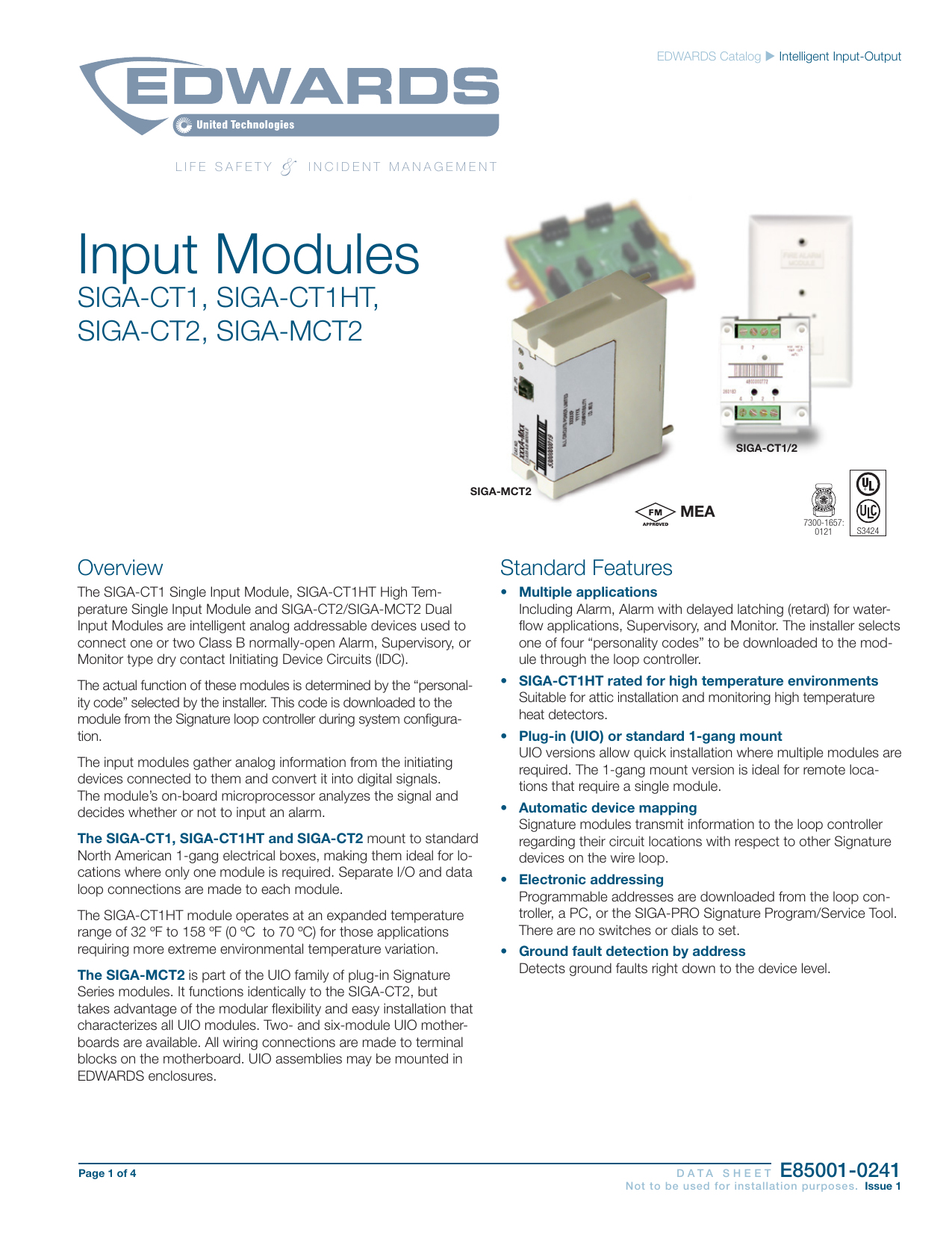
The siga mct2 is part of the uio family of plug in signature series modules. Before replacing a siga cc1 module tag the wires to ensure correct reconnection. Siga ct1 wiring diagram wiring diagram is a simplified all right pictorial representation of an electrical circuit. To wire the module. Siga ct1 wiring diagram ge security vigilant vs1 technical reference manual view and download ge security vigilant vs1 technical reference manual online vigilant vs1 smoke alarm pdf manual. Adjoining cord paths could be shown around where particular receptacles or fixtures have to be on an usual circuit.
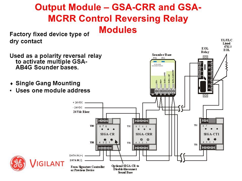
Separate io and data loop connections are made to each module. Click on the image to enlarge and then save it to your computer by right clicking on the image. The siga cc1 module does not supervise the riser. Variety of siga ct2 wiring diagram. It functions identically to the siga ct2 but takes advan. Wiring connections are made to the terminals on the motherboard see wiring diagram.
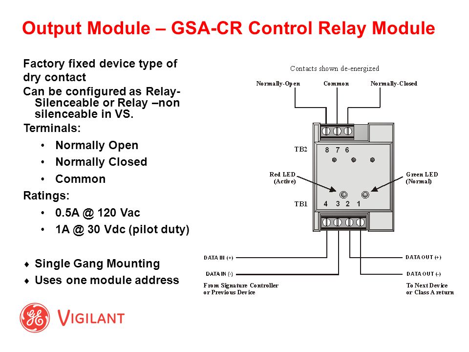
It shows the elements of the circuit as simplified forms and also the power and also signal links between the tools. The siga ct1 and siga ct2 mount to standard north american 1 gang electrical boxes making them ideal for locations where only one module is required. It shows the components of the circuit as simplified shapes and the capability and signal contacts along with the devices. About 6 mm from the ends of all wires that.
Gallery of Siga Ct1 Wiring Diagram