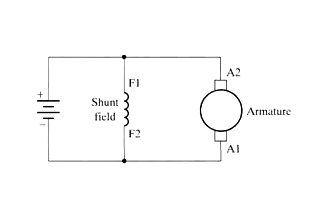
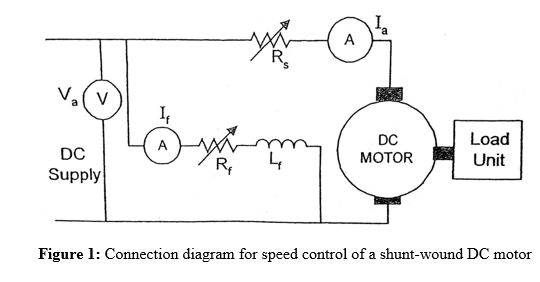
Use figure 1 if your motor has a single voltage shunt field. First one is separately excited dc motor and self excited dc motor.
Shunt Wound Motor Operation Instrumentation Tools
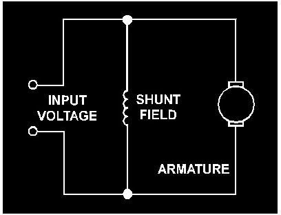
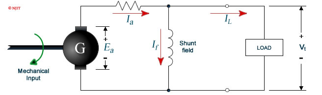
Shunt wound dc motor wiring diagram. Motor connections your motor will be internally connected according to one of the diagrams shown below. A dc shunt motor also known as a shunt wound dc motor is a type of self excited dc motor where the field windings are shunted to or are connected in parallel to the armature winding of the motor since they are connected in parallel the armature and field windings are exposed to the same supply voltage. Since they are connected in parallel the armature and field windings are exposed to the same supply voltagethough there are separate branches for the flow of armature current and field current. In electrical terms parallel is generally denoted as shunt. A dc shunt motor also known as a shunt wound dc motor is a type of self excited dc motor where the field windings are shunted to or are connected in parallel to the armature winding of the motor. The dc shunt wound motor running on direct current has its field windings placed in parallel to the armature.
Lexus v8 wiring diagram. This video will walk you through the connections for a shunt dc motor and demonstrate how it runs without a physical load connected to the shaft of the motor. Ac outlet wiring diagram. Jazz bass pickup wiring diagram. That is the reason behind naming it a dc shunt motor. Wiring diagram 391 views.
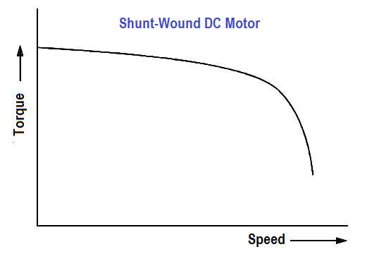
It shows the components of the circuit as simplified shapes and the facility and signal contacts together with the devices. Wiring diagram 11 views. Dc shunt motor speed control characteristics electrical4u. 1 1999 ford ranger pcm wiring diagram. The self excited motors are further classified as shunt wound or shunt motor series wound or series motor and compound wound or compound motor. Motor wiring diagram dc.
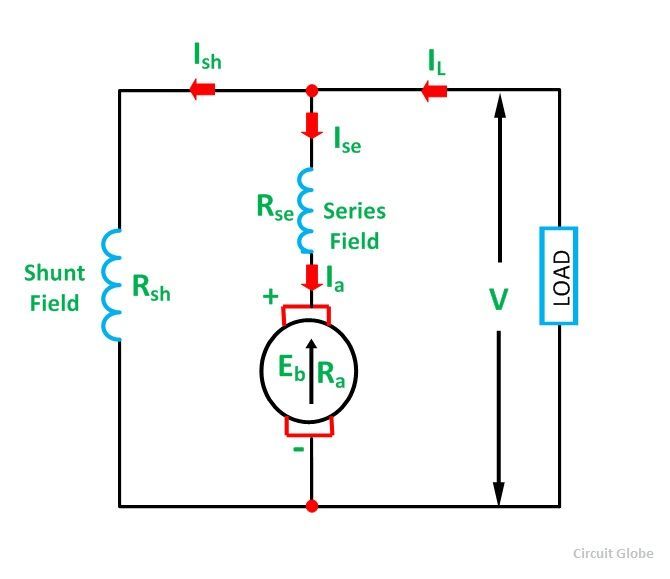
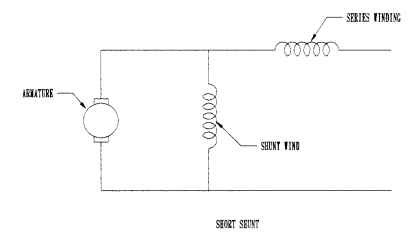
In case of short shunt compound wound dc motor the shunt field winding is connected in parallel across the armature winding only. Shunt wound dc motor wiring diagram wiring diagram is a simplified standard pictorial representation of an electrical circuit. This parallel configuration allows independent path of current for field winding and armature. Use figure 2 if your motor has a dual voltage shunt field. These connections are in accordance with nema mg 1 and american standards publication 06. The dc shunt motor circuit diagram is shown below and the flow of current and voltage being supplied to the motor from the supply can be given by itotal e.
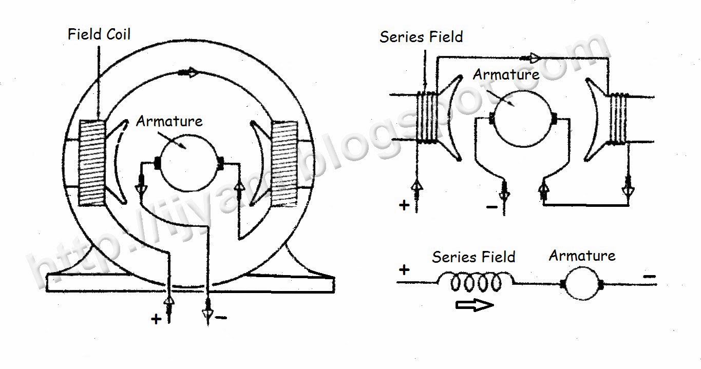
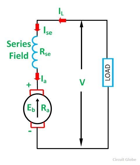
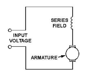
Same voltage is applied to both shunt winding and armature in this motor. Dc shunt motor circuit diagram in case of the shunt wound dc motor this current supply will divide into two ways like ia ish where ia will supply throughout the ra resistance armature winding. And series field coil is exposed to the entire supply current before being split up into armature and shunt field current as shown in the diagram below. Short shunt compound wound dc motor. Wiring diagram 7 views. Types of dc motor a direct current motor dc is named according to the connection of the field winding with the armaturemainly there are two types of dc motors.
Shunt wound dc motor wiring diagram. Wiring diagram 129 views.
Gallery of Shunt Wound Dc Motor Wiring Diagram