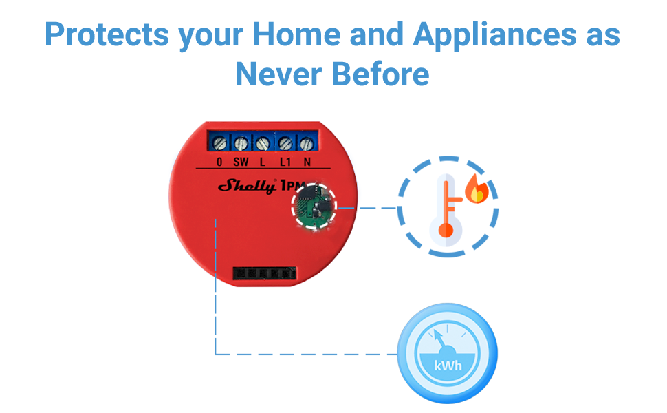
The shelly 1 comes with firmware pre installed to use with the shelly app for iphone and android and the shelly cloud. These devices can support loads up to 16 amps and the only difference between the shelly 1 and shelly 1pm is that the 1pm also has power monitoring so that you can see at a glance the amount of power being consumed by the devices or lighting connected to it.

Support For Shelly Dimmer Issue 6914 Arendst Tasmota
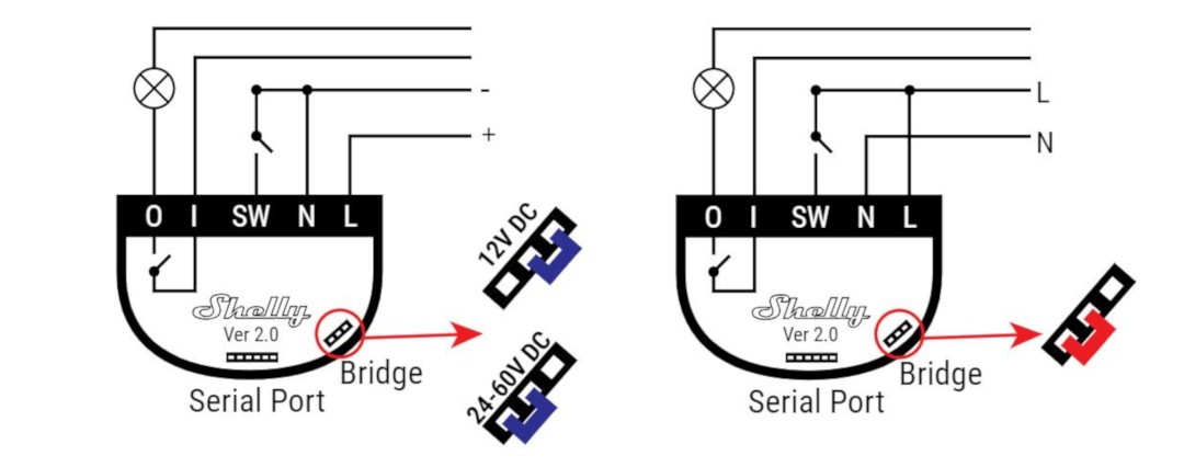
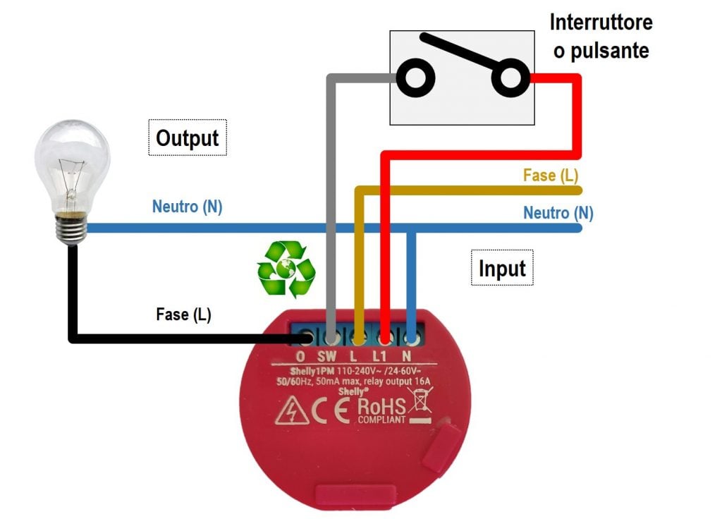
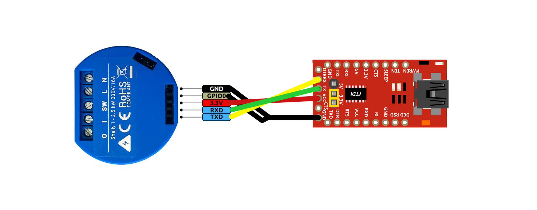
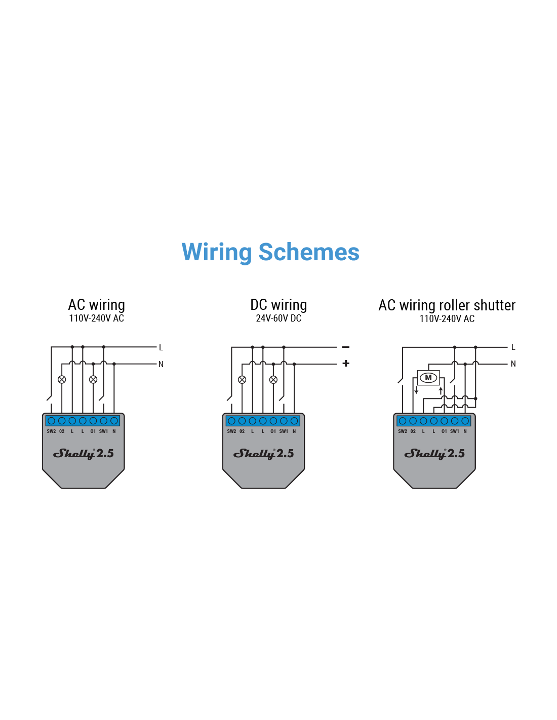
Shelly 1pm wiring diagram. Connect shelly 1 with the usb to uart convertor following the pinout diagram below. Shelly 1 relay wiring diagram for light switch. N goes to neutral required l and i and the linelive input on the light switch which you determined above connect to linehot. We developed shelly 1 with an integrated web interface for device management and secure ota update. Welcome to the forum. Consumption history anywhere at anytime.
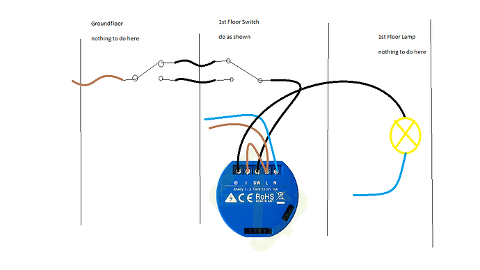
Anyhow even your suggestion would work but you would not see at the shelly app if someone switched on the lamp via the push button. As stefan already stated. It behaves pretty much like any other off the shelf smart home product in that regard. Sw connects to the light switch input previously connected to load light o connects to the non hot load wire previously connected to the light switch. This device allows you to monitor the status and history as well as the current and. Shelly 1 knows your location gives you high security and provides device access control.
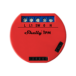
Any work on low voltage grid are dangerous and can be fatal. The shelly 1 is about the size of two oreos stacked on top of each other which allows it to easily hide behind your existing switches. Modify a decora rocker switch to a momentary switch with ease create a secondary long press action to toggle additional devices andor automations in your home. Therefore have this work carried out by qualified electricians. The most intelligent device you can have. Connection diagrams shelly 1 continuation.
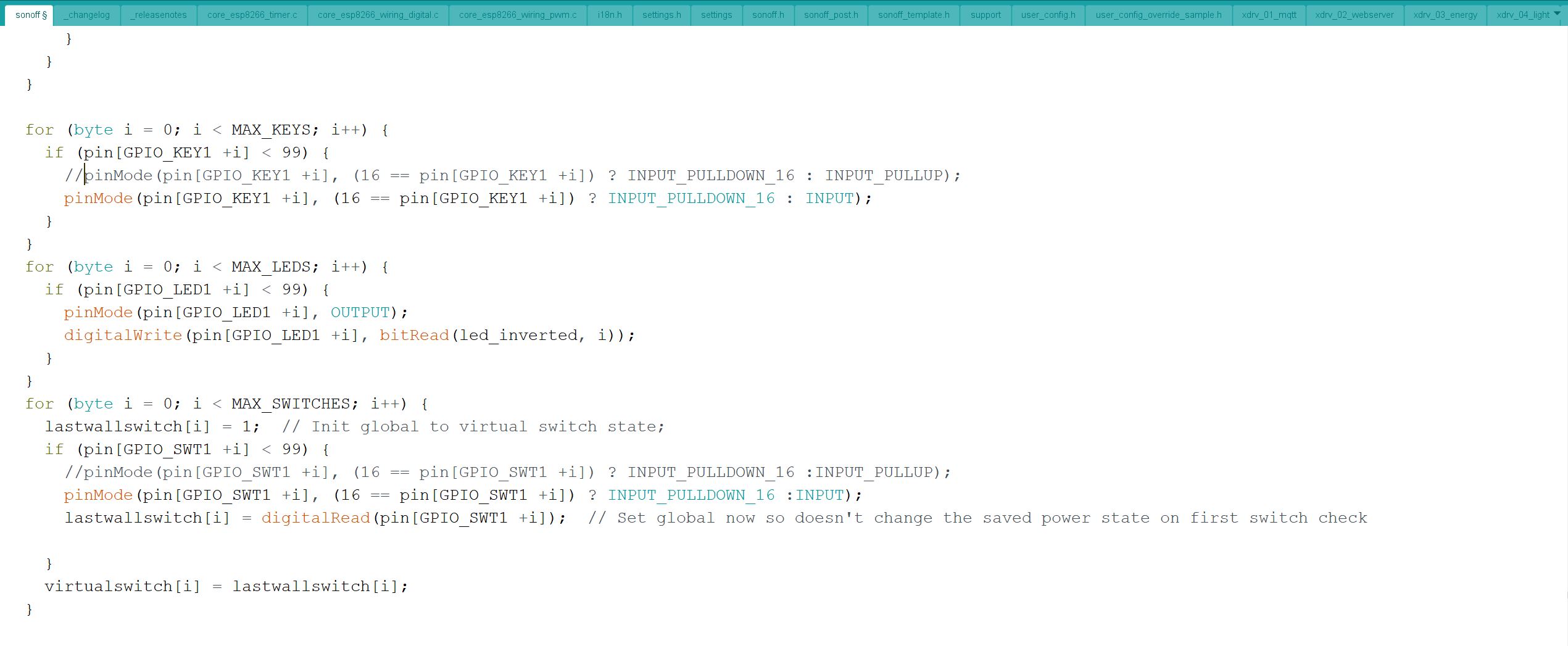
You can set your weekly schedules for onoff without the need of any additional equipment. The standard way would be to connect the output of the push button to the sw input of the shelly and the o output of the shelly to the impulse relay. Expand your shelly1 smart switch. Usb to uart convertor. We developed shelly 1pm with an integrated web interface for device management and a secure ota update. In order to boot the esp in flash mode gpio 0 must be connected to gnd when powering on the device.
Steps for flashing the mcu. What is shelly 1pm. These schemes are for understanding and are not a do it yourself guide.
Gallery of Shelly 1pm Wiring Diagram


.jpg)