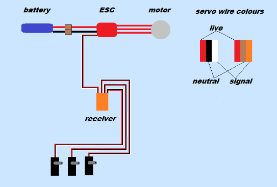
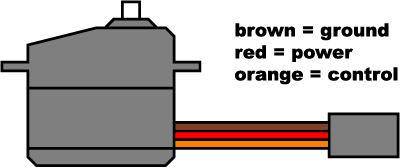
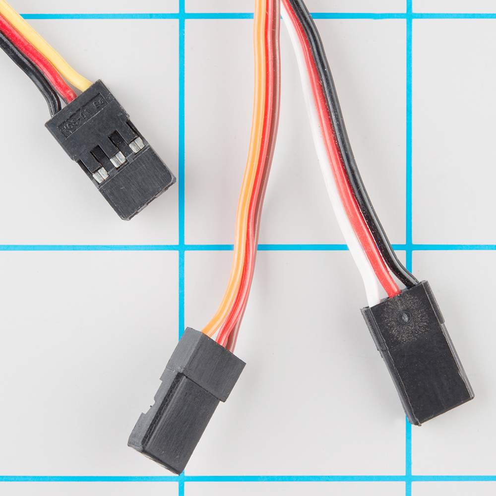
You can mix futaba servos with an airtronics receiver mix hitec jr servos with a futaba receiver etc. In futaba hitec and jr radio servos the servo and battery connections have the same polarity and signal wiring although the connectors are slightly different.
Definitive Wiring Diagrams For Becs Rx Servos Motors Etc
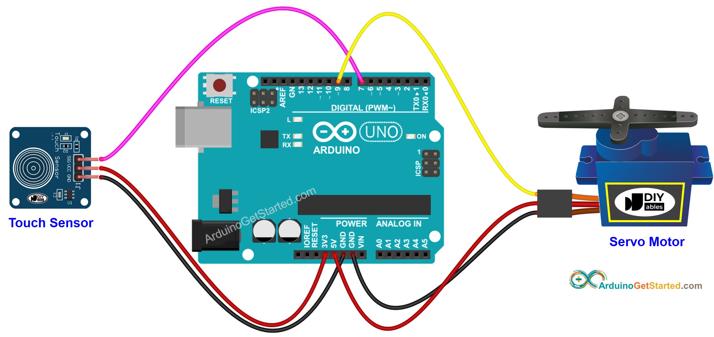
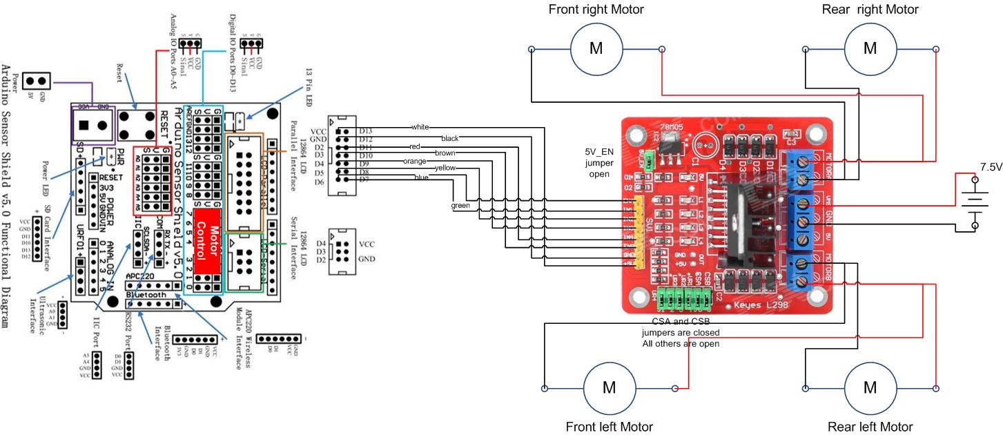
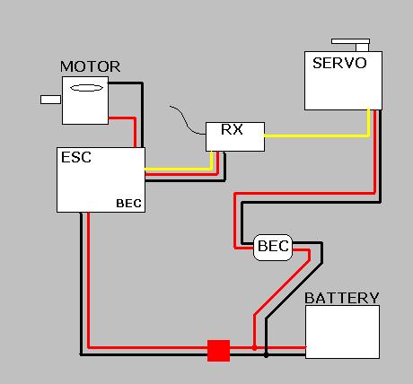
Servo wiring diagram. As long as you are careful about polarity. You can mix futaba servos with an airtronics receiver mix hitec jr servos with a futaba receiver etc. Somewhere along the line the wiring didnt become compatible. Variety of servo motor wiring diagram. A wiring diagram is a simplified conventional pictorial depiction of an electric circuit. Sometimes wiring diagram may also refer to the architectural wiring program.
June 4 2019 by larry a. This is called pulse coded modulation. The angular position of the shaft is determined by the duration of a pulse that is applied to the control wire. The simplest approach to read a home wiring diagram is to begin at the source or the major power supply. The servo typically requires pulse every 20 milliseconds 02 seconds. A wiring diagram usually offers info regarding the loved one placement and also setup of gadgets as well as terminals on the devices to assist in building or servicing the tool.
As long as the coded signal exists on the input line the servo will maintain the angular position of the shaft. For futaba hitec and jr radio the servo and battery connections have the right polarity and signal wires although the connectors are physically different. The wiring diagram on the opposite hand is particularly beneficial to an outside electrician. It shows the components of the circuit as streamlined forms and the power and signal connections in between the devices.
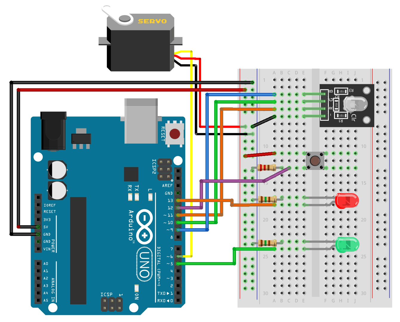
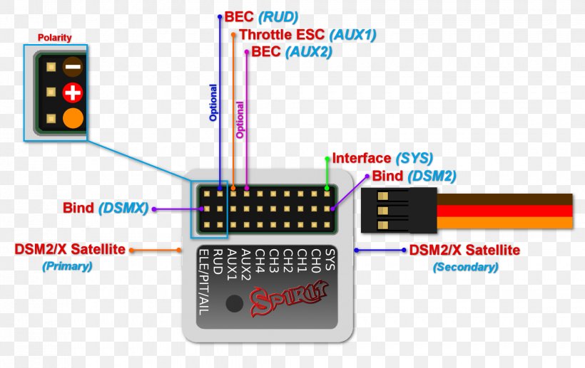
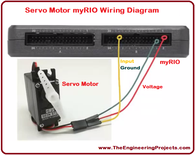
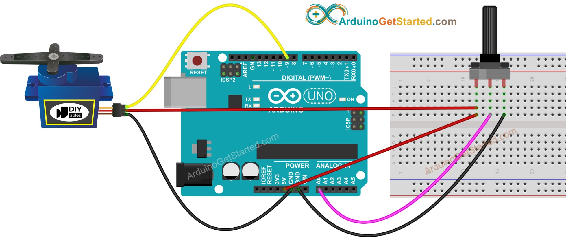
Gallery of Servo Wiring Diagram