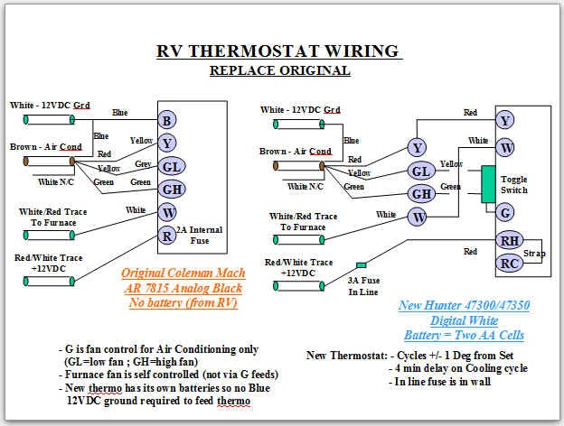
Cut sheet sensor switch wiring diagram sensor switch. Read below this video shows you how to wire an occupancy sensor cm pdt 9 and power pack pp 20 by acuity controls.

Connectivity Of Proximity Sensors
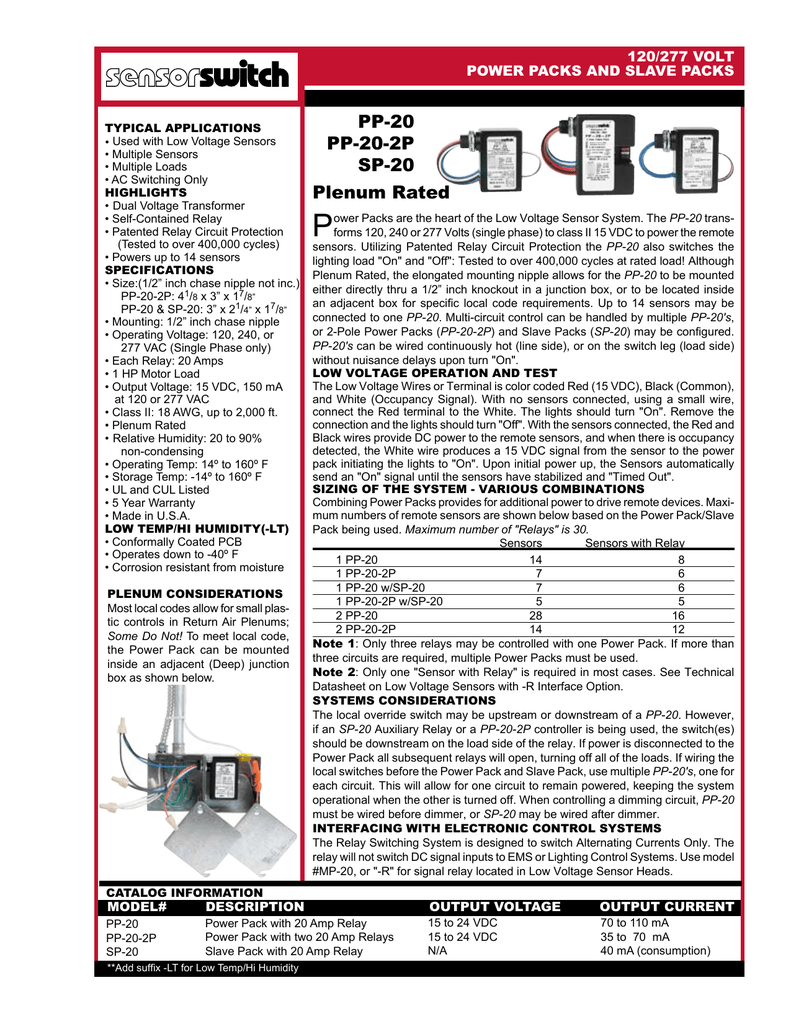
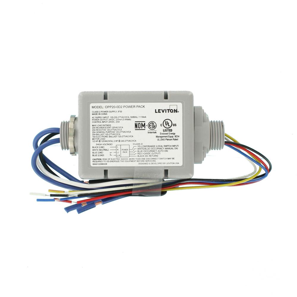
Sensor switch pp20 wiring diagram. Click add to cart to buy sensor switch pp20 power pack. 745975809592 nlight power pack sespp20 sensor switch pp20 accessories occupancy sensors lighting. The pp20 transforms 120 240 or 277 volts to class ii 15 vdc to power the remote sensors. Power packs are the heart of the low voltage sensor system. Wiring diagrams blk 120 v pp20 orn 277 v blk 120 v pp20 orn 277 v. It doesnt matter which one.
4 in other users carts. 6 multiple sensors controlling one circuit multiple sensors controlling two circuits. Pp 20 sp 20 pp 20 2p 120277 vac power packs slave packs n h n pp 20 load red switch blk wht wht blk orn blu blu 6 2. Pp20 power pack with 20 amp relay by sensor switch. Fixture ballast or load 2 fixture ballast or led driver load 1 fixture ballast or led driver blk 120 v pp20 orn 277 v multiple sensors ie wv 16 cm 9 class 1 connections sp20 pp20 auto on load manual. Coming from the power pack you have 2 blue wires.
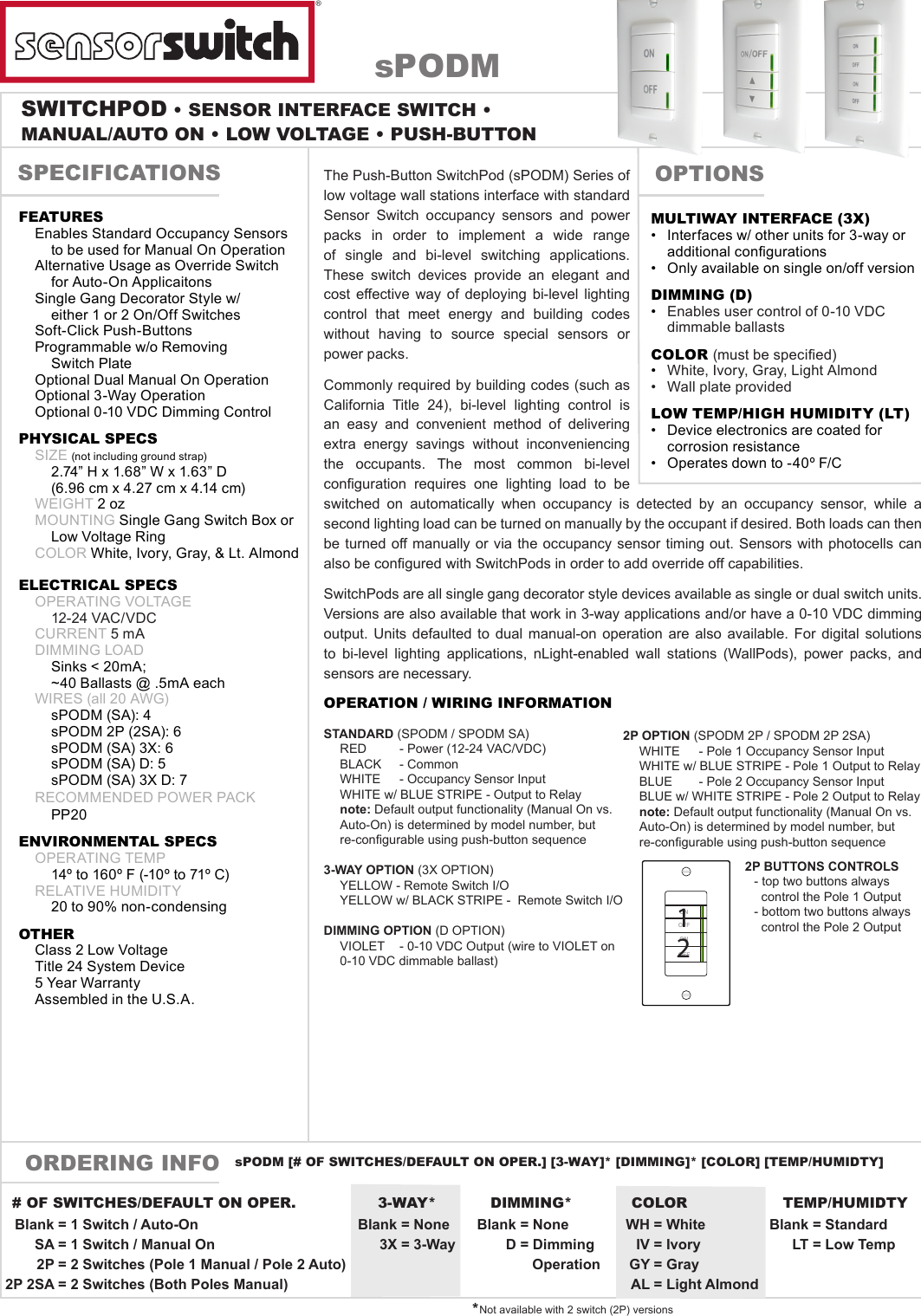
Wiring diagrams d adc dimming options r relay option. Wall switch sensor wsx wall switch with dimming wsx d switch interface. Utilizing our patented relay circuit protection the pp20 also switches the lighting load on and off.
Gallery of Sensor Switch Pp20 Wiring Diagram