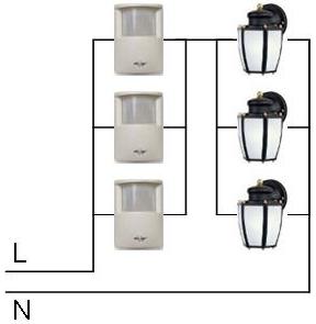
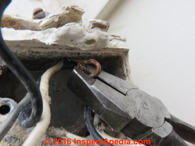
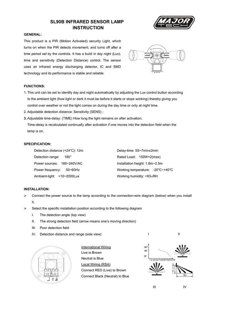
Wiring diagram for a typical motion sensor or security light the installation instructions include this simple schematic illustration adapted with added remarks show how the motion sensor light assembly will mount to the weatherproof electrical box once that box is in place on the wall. Step 4 connect the ground wire from the dusk to dawn security light fixture to the ground wire in the wall box using a wire connector.

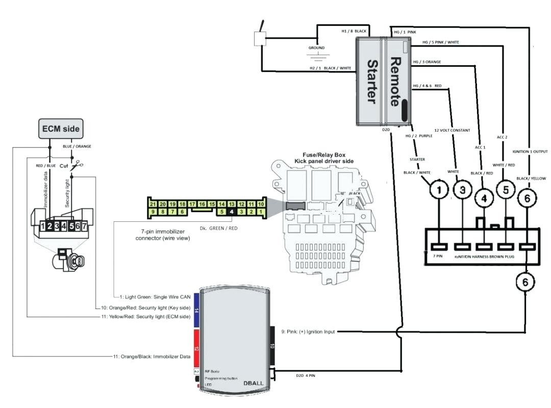
Closed Circuit Television Wiring Diagram Wireless Security
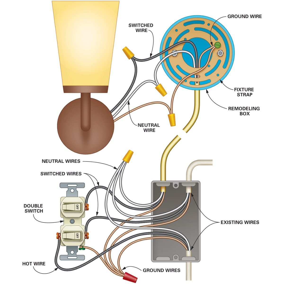
Security light wiring diagram. The attic space is not used and is full of blown insulation. If this is not evident with a mains tester screwdriver and turning the electrical supply back on by probing either side of the switch where the wires are connected and secured with small brass screws ascertain which side of the switch is the live feed wire. Red wire is the load or the outgoing power to the light fixture. Fortunately security lights are usually simpler to wire than other light wiring projects since no switch is needed. Security lights go on and off automatically by motion sensor or if you are not getting this type they are photo cell meaning off during the day. Wiring option 1 the only clear run i can identify is within the webs of the trusses.
Black wire is the line or the incoming circuit power. You can do this fairly quickly and avoiding spending big money on an electrician. White wire is the neutral wire which is typically shared or connected with the light fixture and the sensor or detector. Typical wiring connections for a security light sensor. I would like to add an additional security light in a gable end of my home. Wall switch wiring diagram.
The gasket comes packaged with the security light and is required in order to prevent water from getting behind the fixture and into the wiring box. Green wire or bare wire.
Gallery of Security Light Wiring Diagram