Page 11 see the wiring diagram later on in this section. Once the wiring has been completed position the it500rx receiver over the electrical box fixing holes.

User Manual Salus Rt 520 Rf 2 Pages
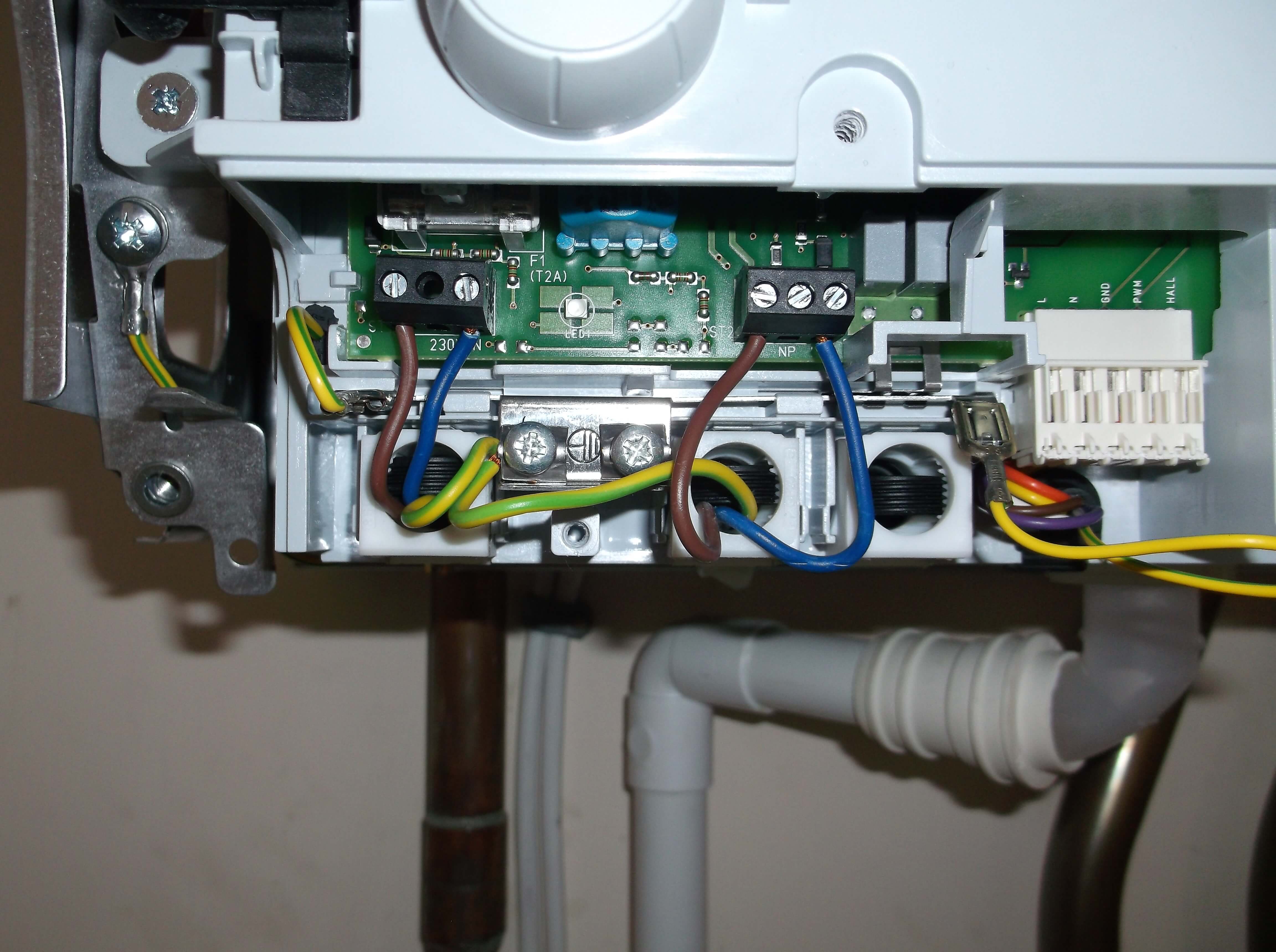
Salus it500 wiring diagram. 48 32 700 74 53. My current thermostat is a honeywell t6360b here is a pic of the connections. Wiring diagram for 2 heating zones. Auto if the it500 is to be used auto in the uk for single zone heating then there is no need to enter system auto configuration. Wiring diagrams for single heating zone. Wiring schematics for system configurations c.
Desk mount option it500 it500 internet thermostat importer. 48 32 750 65 05 if you prefer. Not registered an account yet. I dont know why the yellow and green wire is connected to the first screw on the left. Salus at salus controlspl if you prefer polish language. Please click the button below to register your account.
230v 230v 230v 230 v switching boiler 230 permanent 230 boiler 230 potential free switching boiler 0 230v 230v boiler 230v. Ovo customers register here. I want to replace my t6360b honeywell thermostat with a digital salus it500. Register bookmark this login page. The it500 controls your heating and hot water from anywhere via your smartphone or laptop. Constant green light when the it500 is connected to the salus controls server.
Salus it500 installation manual. It500 thermostat pdf manual download. Manual wiring diagram declaration of conformity. It500 installer manual 07 i you require port 80 and 2165 udp open on the router. Carefully position any wiring back into the electrical box and secure the it500rx receiver using the existing screws. Rolna 4 43 262 kobielice poland wwwsalus controlseu salus controls is a member of the computime group.
Salus controls plc salus house dodworth business park whinby road barnsley s75 3sp united kingdom dystrybutor of salus controls. Page 11 selecting your system configuration based on your system wiring on page 4. View and download salus it500 installer manual online. It500 user reference manual.
Gallery of Salus It500 Wiring Diagram