2 matguard pressure sensitive safety mat system installation and user manual section 1 storage and handling page 4 section 2 system description page 5 section 3 applications page 8 section 4 specifications page 10 section 5 installation design page 14 section 6 installation and commissioning page 26 section 7 use page 36 section 8 maintenance page 37. Nsd safety mats installation manual heavy duty and flexible safety mat system.
2008 Toyota Tundra 5 7l Neutral Safety Switch Wiring
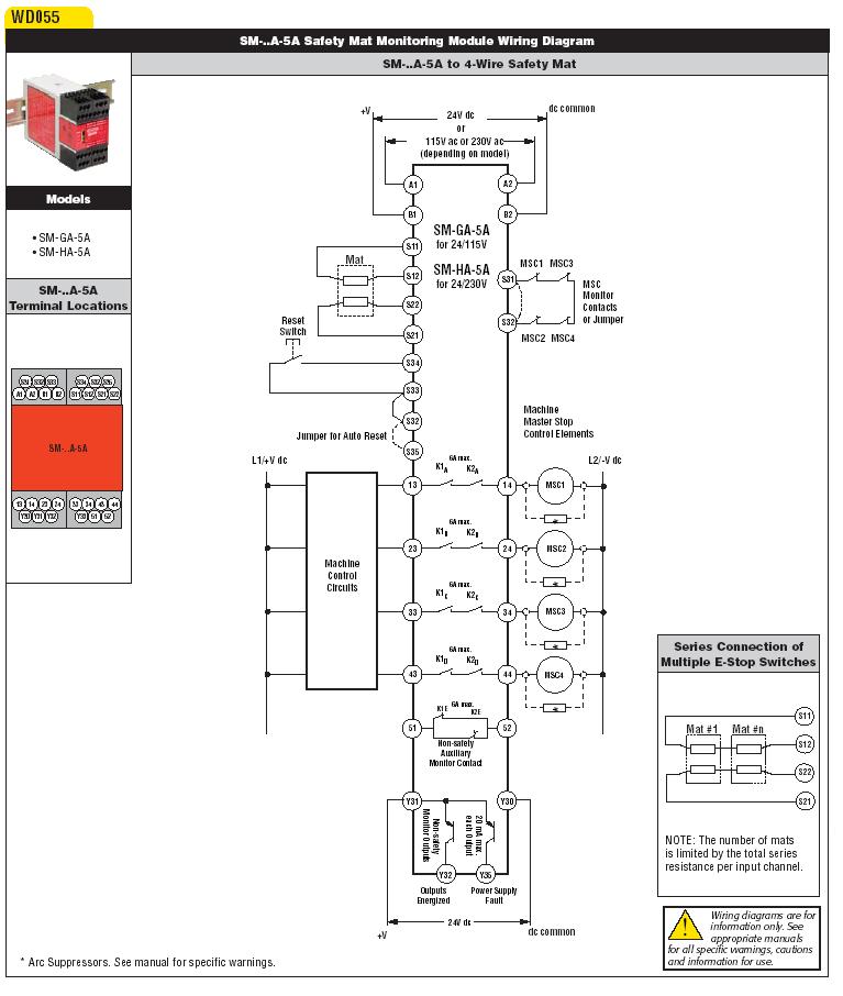
Safety mat wiring diagram. Variety of safety mat wiring diagram. Our bulletin 440f matguard safety mats are pressure sensitive safeguarding products that we designed to detect the presence of people on the sensing surfaces. These mats have two conductive hardened steel plates that are held apart by non conductive compressible separators. Customized shapes and sizes of mats is our specialty with large 6 x 12 single mat capability. This is suggested for easing installation and diagnostics for. Using the formula t t1 t2 35 ms 485 ms 520 ms 0520 s s 1600 x 0520 1200 mm 832 1200 mm 2032 mm sensor mats will be required from 2032 mm right up to the edge of the machine base plate.
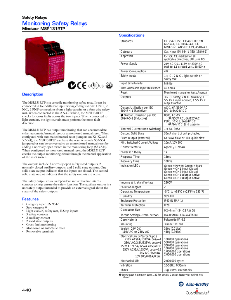
1 single wire safety input input simultaneity infinite input resistance max. Users are required to. A wiring diagram is a streamlined standard photographic representation of an electrical circuit. 24v ac or dc max current thru mat. 543 for use as a presence sensing system within a perimeter guarded area. It reveals the parts of the circuit as streamlined shapes and the power and also signal links in between the tools.
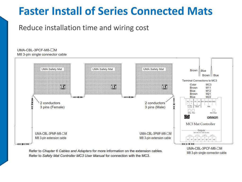
This style system is the traditional style of a normally open no switch mats. 1k ohm the mat system has been designed to promote individual mat homerun wiring back to the mat controller. Wiring diagram next generation guardmaster safety relay gsr bulletin 440r quick reference page safety relay modules input devices output devices sil cl category number pl stop cat. Safety mats two zones. 6 si e stop powerflex 525 2 3 d 0 8 si multifunctional access box mab powerflex 525 2 3 d 0 10 si trojan t15 1794 flex io 2 3 d 0. 2 dual nc 2 dual ossd or safety mats and 1 single wire safety input sici.
9 safety mats are to be fixed anchored in position. 1 dual nc 1 dual ossd or safety mats glp. 900 ω reset configured automaticmanual or monitored manual reset pulse. Read this document and the documents listed in the additional resources section about installation configuration and operation of this equipment before you install configure operate or maintain this product. 75ma mat resistance when stepped on. Or 1 dual ossd and 1 singlewire safety ememd.
It shows the components of the circuit as streamlined forms and the power and also signal connections between the devices. The category 3 controller meets all safety standards. Max voltage applied to mat. A wiring diagram is a streamlined traditional photographic depiction of an electrical circuit. Assortment of safety mat wiring diagram.
Gallery of Safety Mat Wiring Diagram