Minka aire concept ii ceiling fan hard wiring help please with ceiling fan reverse switch wiring diagram image size 600 x 356 px and to view image details please click the image. The wiring diagram above is similar to the ones shown earlier.

Motor Wiring Reverse Switch Electrical Diy Chatroom Home
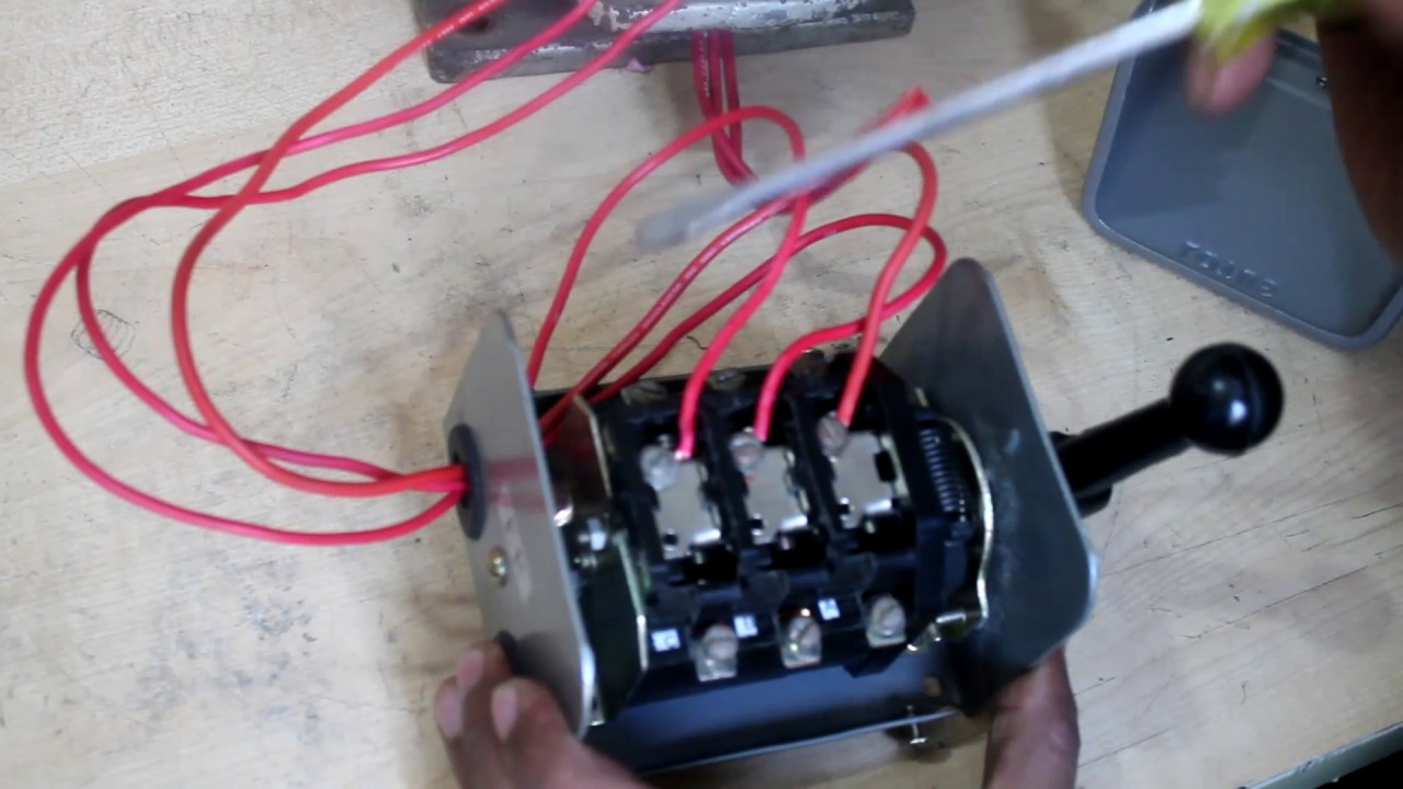
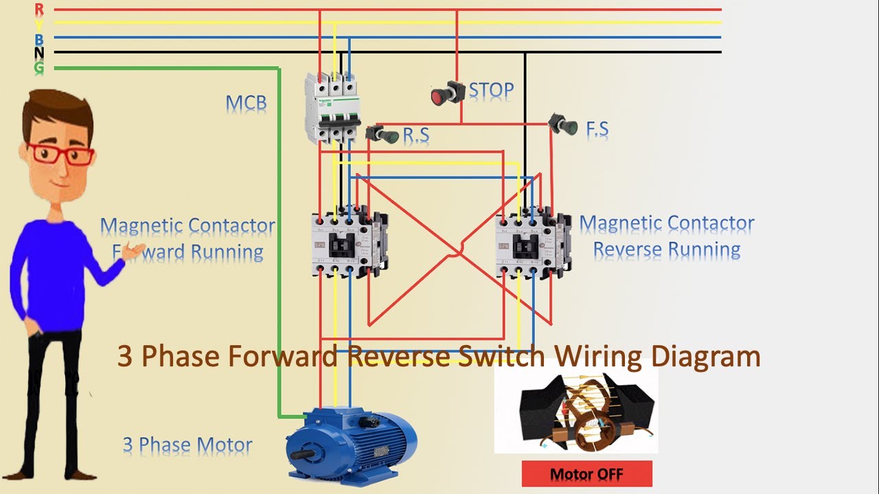
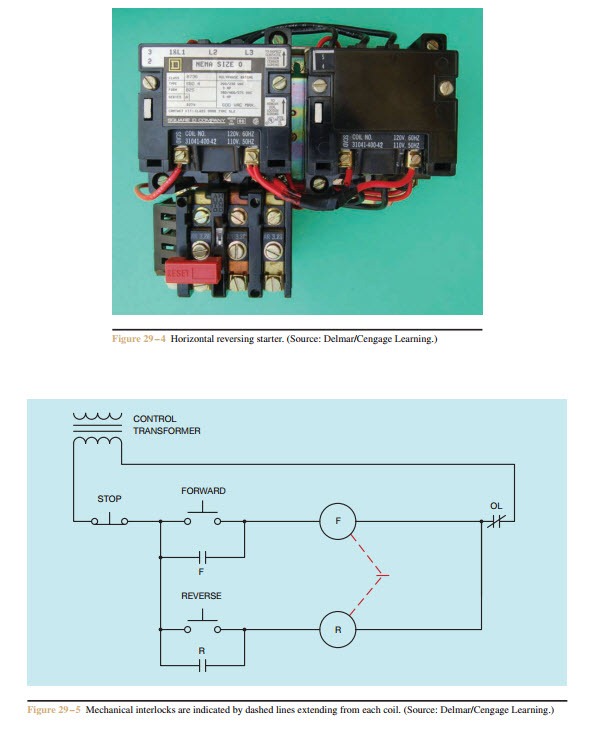
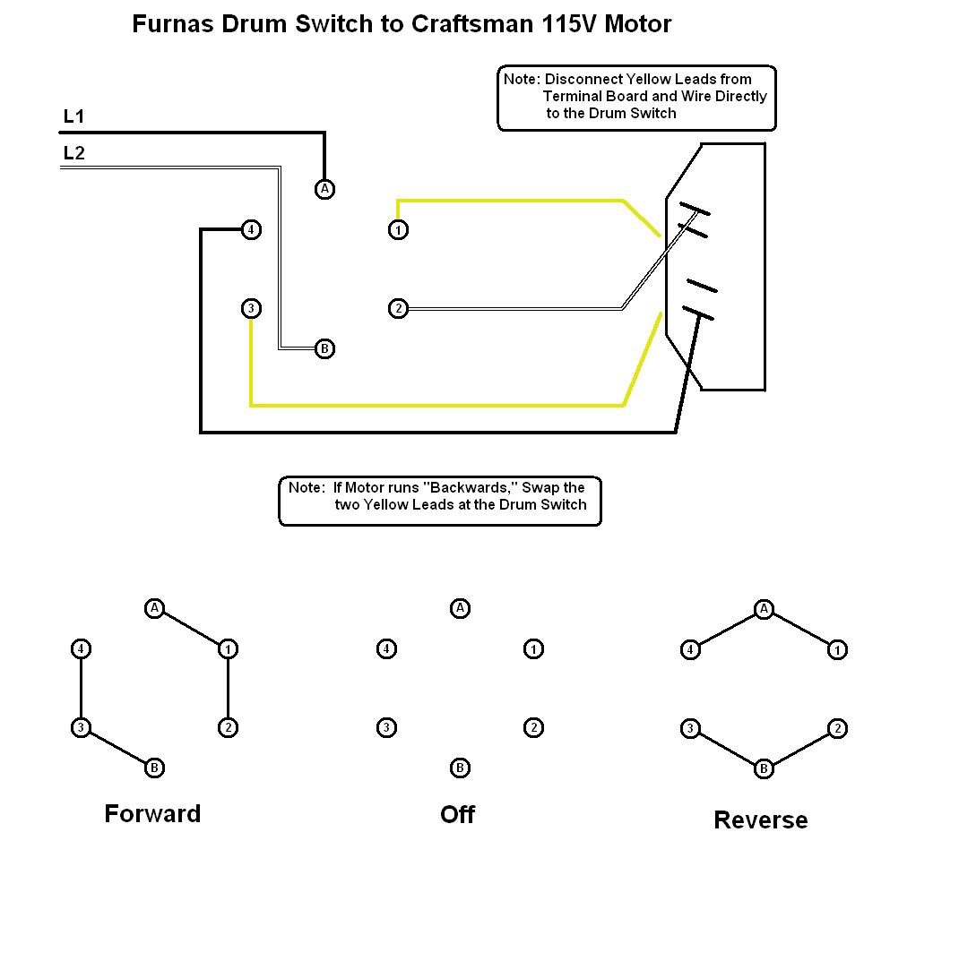
Reversing switch wiring diagram. Electric motor reversing switch wiring diagram what is a wiring diagram. A red wire connected to the pin 6 runs to a limit switch that cuts out power when the cable reaches the top the same red wire from the limit switch joins with the wire from the capacitors and continues to the motor. Two additional switches have been inserted. Figure 1 shows a picture of the drum switch and figure 2 shows a diagram of the drum switch contacts. To read a wiring diagram first you need to know exactly what basic components are included in a wiring diagram and also which pictorial icons are used to represent them. Figure 2a shows the drum switch contacts when the switch is in the reverse position figure 2b shows the contacts when the switch is in the off position and figure 2c shows the contacts when the switch is in the forward position.
A wiring diagram is a streamlined standard photographic representation of an electrical circuit. Are all dpdt rocker switches the same. Wiring diagram of a dpdt connected motor plus two snap action switches for user control with limit stops. Wire a dpdt rocker switch for reversing polarity. When you need to control a dc motor such as a dc linear actuator you usually need to be able to swap the polarity on the wires going to the motor. Assortment of electric motor reversing switch wiring diagram.
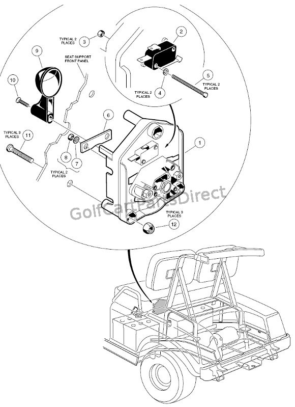
The usual aspects in a wiring diagram are ground power supply cord and link outcome devices switches resistors reasoning entrance lights etc. Ezgo golf cart forward reverse switch wiring diagram manual e books ezgo forward reverse switch wiring diagram you are able to usually rely on wiring diagram as an essential reference that can assist you to conserve money and time. It shows what sort of electrical wires are interconnected and can also show where fixtures and components could be. One switch connects or disconnects the white wire on the bottom terminal. A wiring diagram is an easy visual representation from the physical connections and physical layout associated with an electrical system or circuit. It shows the components of the circuit as streamlined shapes and the power as well as signal links in between the devices.
A double pole double throw switch is used for this purpose but you have to wire it up correctly. Here is a picture gallery about ceiling fan reverse switch wiring diagram complete with the description of the image please find the image you need. And finally a grn wire joins pins 4 1 and 3 then runs up to motor.
Gallery of Reversing Switch Wiring Diagram