Electrical wiring layouts are made up of 2 things. If more than one controller is in operation at the same time controller a takes precedence over controllers b c and d.

How To Replace A Lawn Sprinkler Timer 12 Steps With Pictures
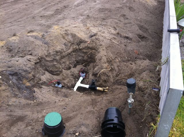
Retic wiring diagram. Refer to the wire size chart below for wire size and maximum lengths. 5 core irrigation cable. The wire nuts create a secure connection between wires and the grease caps will ensure a waterproof seal. The two red wires on the left are going directly into the transformer and there is no power plug. With fencing deep holes need to be dug for the posts and this can often hit the main supply line or wiring. Dual connecting two wire paths 4 of 8 duration.
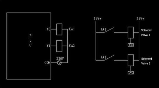
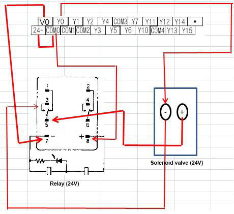
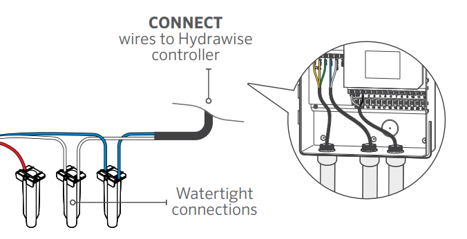
Call us on 0424 133 950 or send us an email at service at lukeslandscaping. To begin wiring at the controller with the power off pull back the outer sheathing exposing the individual wires. Once connected in the water will then again flow to each stations solenoid valve although in some cases it may now. The transformer turns the power from 240 volts which is lethal to 24 volts which will operate a solenoid valve correctly. Ok so assuming you are running off the water mains you will need to run the mp wire to your master valve. Water getting into the wiring often damages the solenoids beyond repair so this small investment will prevent extra expense and hassle.
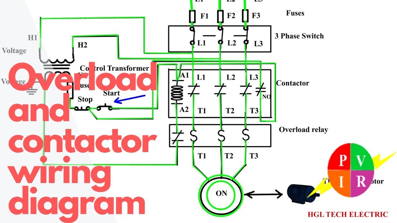
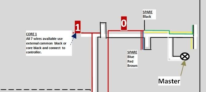
Icons that stand for the parts in the circuit as well as lines that represent the links between them. Different wire can be used to connect the pump start relay to the controller. You will need one individual wire for each solenoid valve and one common wire to be shared by all the solenoid valves. It doesnt matter which wire it connects to on the solenoid. This wiring diagram shows us the wiring for four controllers wired to one pump starter and one common wire for all valves on all four controllers. The equipment and the various trades needed to undertake the majority of problems with home residential retic systems and we are well established in the industry.
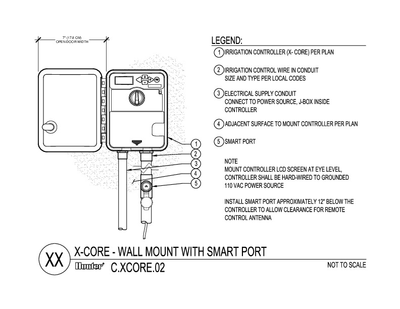
You may have noticed a trend you will always require at least one extra wire. For more information on controllerpsr installation please see support page for specific controller. In the picture below you will see a hard wired retic controller. Wiring can be pain free if the proper steps are taken in planning. Hunter dual two wire installation. A wiring diagram is a type of schematic which makes use of abstract photographic icons to show all the interconnections of parts in a system.
The mainline of a retic system is the pipes that go downstream from the now disconnected master solenoid valve near the water meter all the way to any of the individual solenoid valves that operate any of the stations zones. Subscribe subscribed unsubscribe 99. Controller c will take prece. Controller b will take precedence over c and d. This is the case for all solenoids usually this is the red wire and if you stick with that it will help anyone who comes along to repair it later.
Gallery of Retic Wiring Diagram