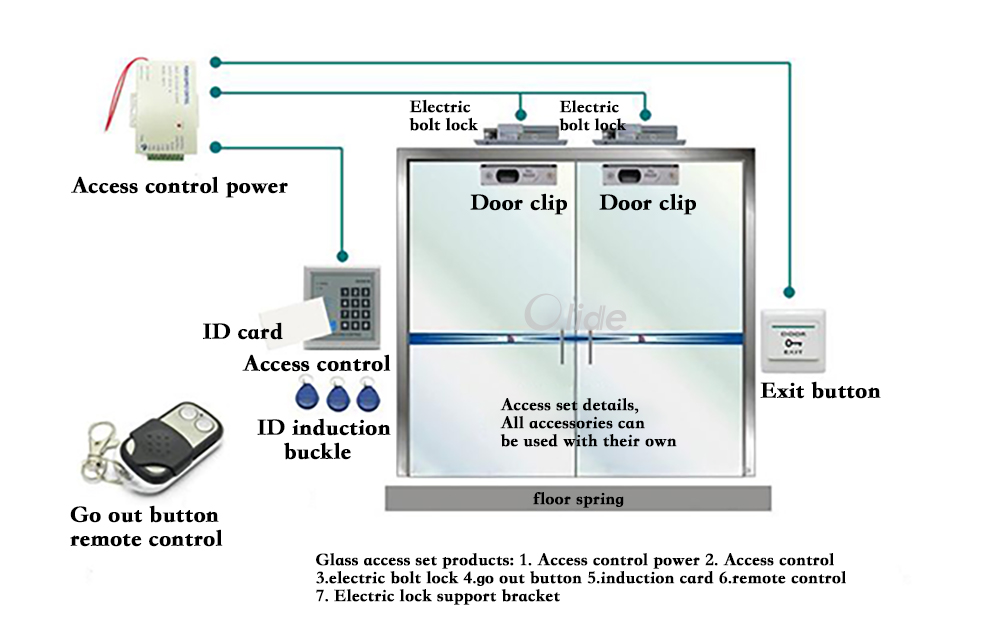
The following common wiring diagrams are available. Door exit button sensor 2.
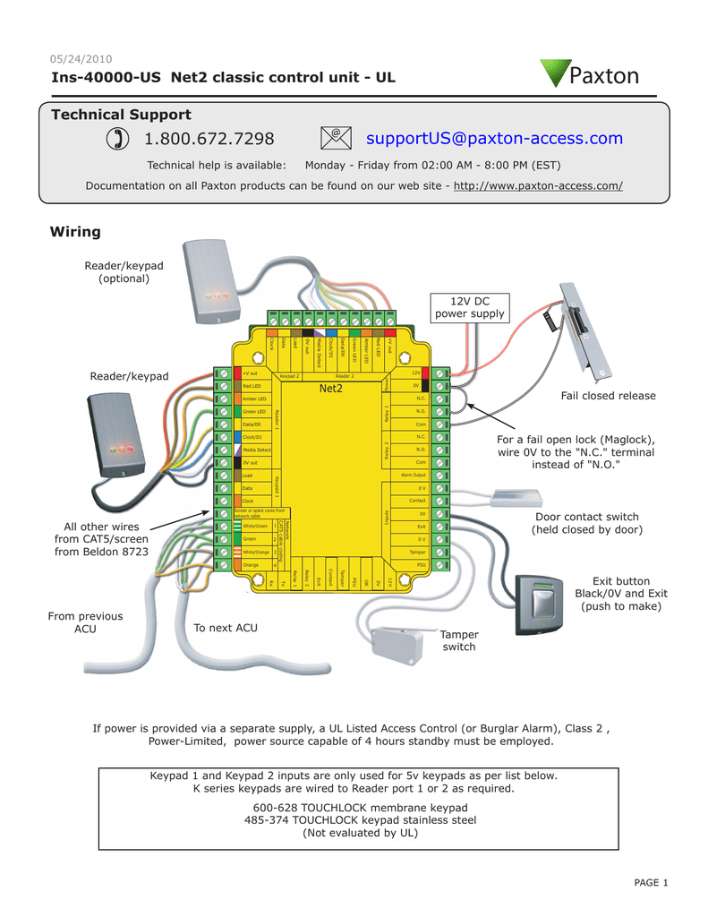
Ins 40000 Us Manualzz
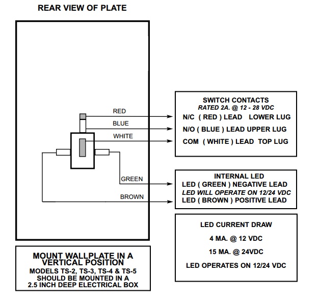
Push to exit button wiring diagram. Mower wire diagram online wiring diagram the contacts are ul listed with 10 amp capacity. Riser diagrams falcon exit devices. Push to exit button wiring diagram. Remote push button with electric latch retraction fire rated application. How to wire an exit button or sensor description. And can sometimes be labeled as led and led but are essentially the same.
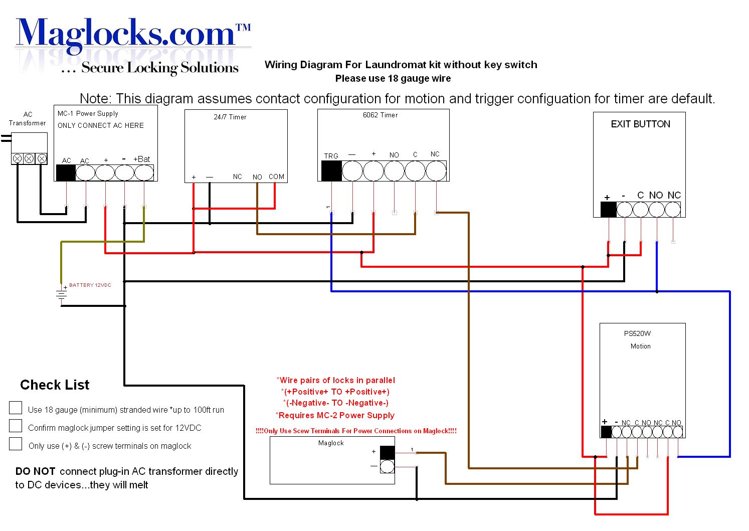
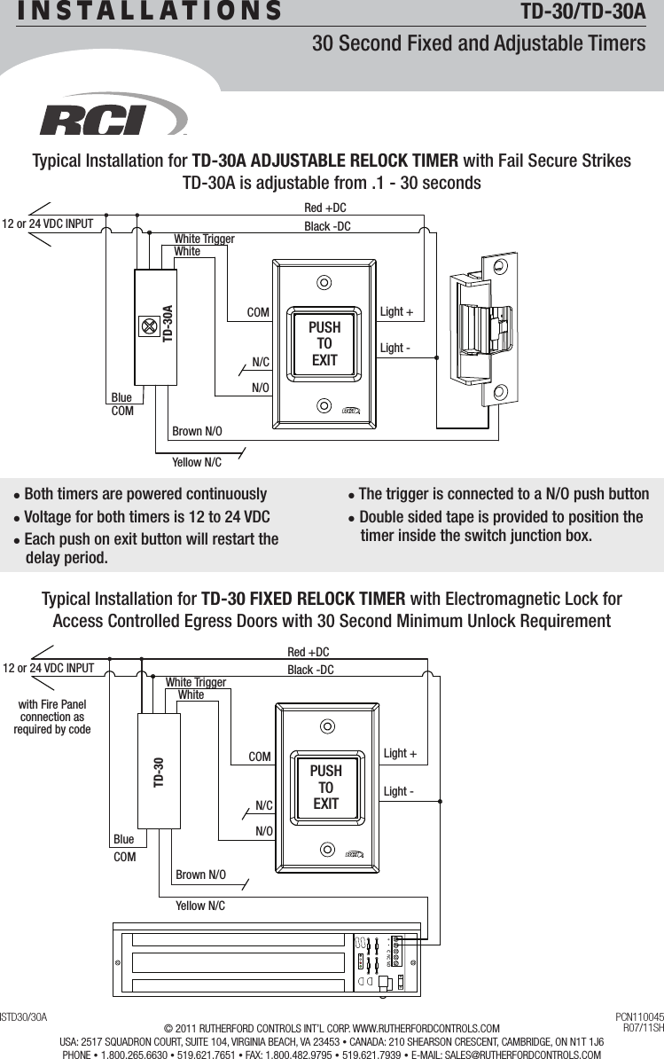
Wiring diagram electromagnetic door lock em lock push button power supply 12v carane ngonek kunci magnet. Electric latch retraction with auto operator. Identification of the wires and a typical wiring diagram showing a power supply motion detector push button and magnalock so as to comply with the boca code for access controlled egress doors. Both the push button contacts and. L the schematic or line diagram includes all the components of the control circuit and indicates their. Single door controlled egress wiring diagram 01 single door digital entry wiring diagram 10 single door dk 26 with door prop alarm wiring diagram 15 single door dk1 11 xms dt 7 wiring diagram 20 single door dk 26 remote release wiring diagram 14 single door dk 26 unl 24 and dt 7 wiring diagram 18 single door dk 26 using the hard code to toggle lock off and on wiring diagram.
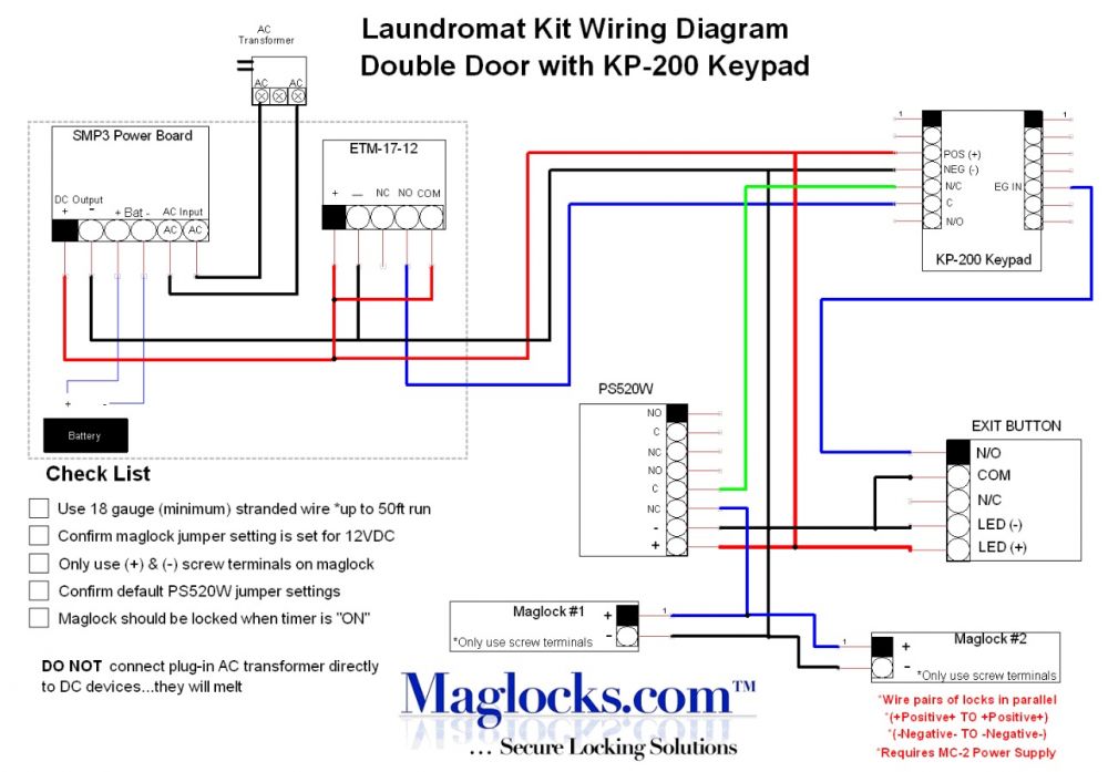
Wiring instructions fail secure strike with one button power supply push button no fail secure strike polarity insensitive depressing the push button would close the circui t allow power to flow and release the strike. There is a point to note about the internal design of the unit. Connect the common from the keypad to the normally close connector on the push button 21. If you are not completely familiar with installing rex buttons kisi highly recommends that you make your connections one pair at a time. On the magnetic lock. Connect an extra piece of wire to the common connector on the push button 22.
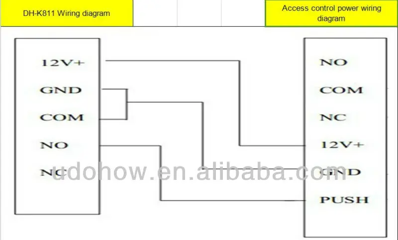
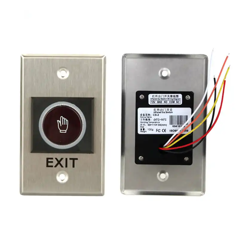
This wiring diagram is to describe where to wire door exit button sensor to dahua access controller. Power supply may be ac or dc depending on the requirements of the strike. One single door with panic bar. Typical wiring diagrams for push button control stations 3 genera information at each circuit is illustrated with a control circuit continued schematic or line diagram and a control station wiring diagram. Essex electronics stainless steel vandal resistant request to exit buttons can be used to control an automatic door electric lockstrike magnetic lock or any electrically controlled device. Push to exit button wiring guide.
Gallery of Push To Exit Button Wiring Diagram