Bold lines indicate action to be taken in step shown. Connect wire from terminal hof water feeder to terminal 1on lwco.

24 Fe Poe Plus 2 Ge With 2 Combo Sfp Switch Computex Biz
Pse 802 24 wiring diagram. Pse 802 24 control unit pdf manual download. 751p mt 24 pse 801 120 pse 802 24 pse 801 m 120 pse 802 m 24 pa 800 u for repl. Select a wiring method after reviewing the wiring diagrams and notes. Probe control lwco for steam boilers. Kg ps 801 u 120 pa 800 u 354141 probe 0523 ps 802 u 24 ps 851 m u 120 ps 851 u 120 ps 802 m u 24 ps 801 m u 120 750p mt u 120 pse 801 m u 120 pse 802 m u 24 pse 801 u 120 pse 802 u 24 751p mt u 120 752p. View and download mcdonnell miller pse 802 24 instruction manual online.
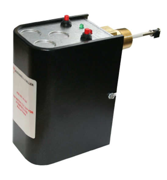
Mcdonnell miller 153602 lwco pse 802 m 24 electronic 24v low water cut off w manual reset steam the series pse 800 m manual reset lwco is a new addition to the mcdonnell miller probe type low water cut off group of products. Check to make sure factory supplied jumper is installed between terminals h and c. Dotted black lines indicate internal wiring. These controls are used as the secondary lwco on steam boilers and can be used as the primary lwco on hot water heating boilers. Wiring diagram legends 1. Voltage of new manual reset lwco must be the same as the existing automatic reset lwco.
Pse 802m 24 24 vac na 50 va pse 802m u 24 pse 801m 120 120 vac 75 fla 432 lra 125 va pse 801m u 120 hertz 5060 control power consumption. Connect plug a of wiring harness to receptacle b. Ps 802852 using harness connection ps 802852 using terminal connections d n. Diagram 1 wf2 u 24 ps 802 lwco wn h ps 801 120 lwco uni match water feeder wf2 u 120 field or factory jumper wire p 12345 connect wire from terminal nof water feeder to terminal 2on lwco. Probe part weight model model no.
Gallery of Pse 802 24 Wiring Diagram