Plc digital signals wiring techniques. If equipment that generates electrical noise or heat is positioned in front of the plc as when such equipment is mounted on the back of a panel door allow a clearance of 100 mm or more between the plc and such equipment.
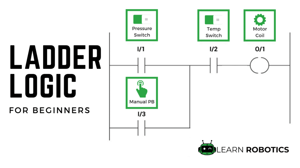
Ladder Wiring Diagram Ladder Logic Examples And Plc
Plc wiring diagram guide. Plc wiring diagram guide a beginner s overview of circuit diagrams. Plc wiring diagram guide. Assortment of plc panel wiring diagram pdf. In this article we are sharing the basic concepts of plc and dcs control systems wiring diagrams for digital input di digital output do analog input ai and analog output ao signals. Wiring diagrams of plc and dcs systems di do ai ao. Collection of plc wiring diagram guide.
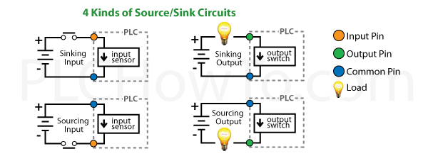
Obtaining from factor a to direct b. This is the first plc training video in the plc wiring series subscribe to our channel so you do not miss each one as it is released. Some connectors are like the one shown and disconnect from the plc while others are fixed to the the plc. When wiring ac supplies. Literally a circuit is the path that permits power to circulation. Plc digital signals wiring techniques ina process plant onoff control is done through the plc or dcs.
A very first appearance at a circuit layout might be complicated but if you can review a train map you can review schematics. It shows the elements of the circuit as streamlined shapes as well as the power as well as signal connections in between the tools. A wiring diagram typically offers details concerning the relative position and plan of devices as well as terminals on the tools to aid in building or servicing the device. Verify that all modules are in the correct slots. A wiring diagram is a simplified conventional photographic representation of an electric circuit. Check module type and model number by inspection and on the io wiring diagram.
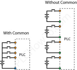
Earth e or symbol. A wiring diagram is a streamlined traditional pictorial depiction of an electric circuit. It is only logical to start with the first wiring circuit in. The below figure is an overview of one discretedigital onoff circuit showing the entire process from the power supply through the sensor and on to the plc. Most plc connections involve connecting to something like the terminal block shown on the right. It shows the parts of the circuit as streamlined shapes and also the power as well as signal connections in between the devices.
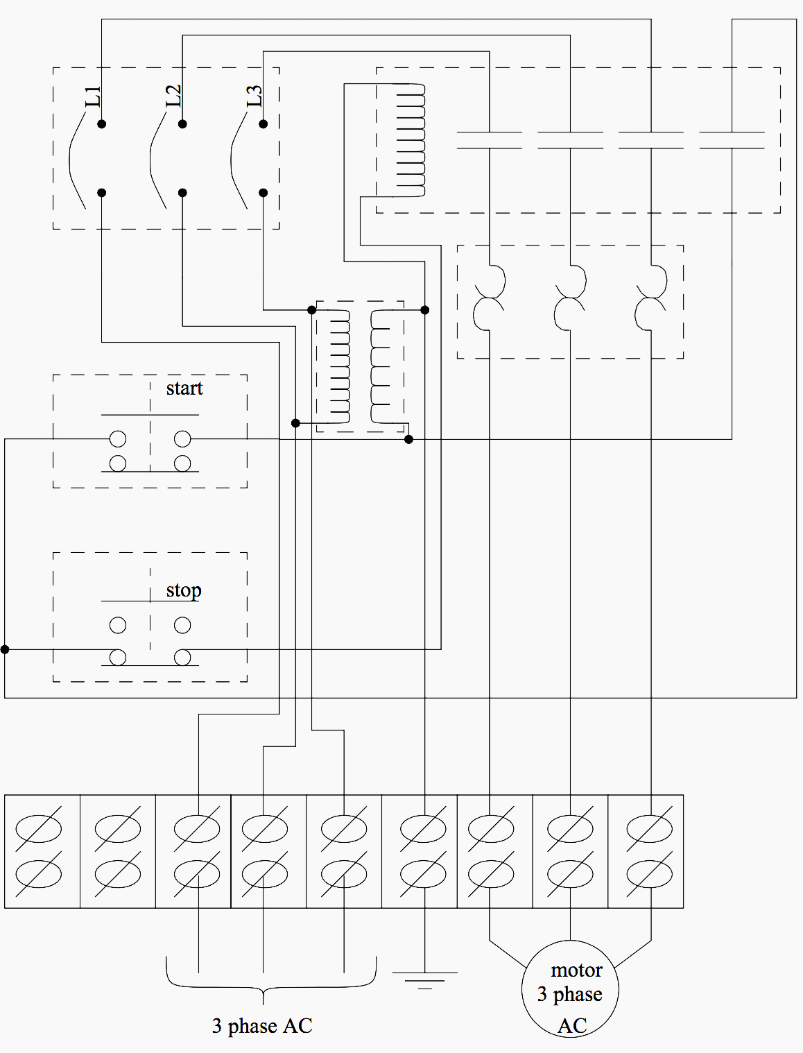
Remove and lock out input power from the controller and io before any plc installation and wiring begins. The objective is the very same. Electrical wiring diagrams of a plc panel transformers to step down ac supply voltages to lower levels power contacts to manually enabledisable power to the machine with e stop buttons terminals to connect devices fuses or circuit breakers will cause power to fail if too much current is. The following are ten recommended procedures for io wiring. Note that these diagrams are without a barrier or isolator fuses and surge protector for keeping it very simple and understandable. November 6 2018 by larry a.
Slide the wires into the slots on the bottom and using the screws found on top you secure the wires.
Gallery of Plc Wiring Diagram Guide