The mks series has proven to be exceptionally reliable since its introduction almost 50 years ago. When using the pf083a and pf113a be sure not to exceed the sockets maximum carry current of 5 a.

Mk S Relays Datasheet Pdf General Purpose Relays
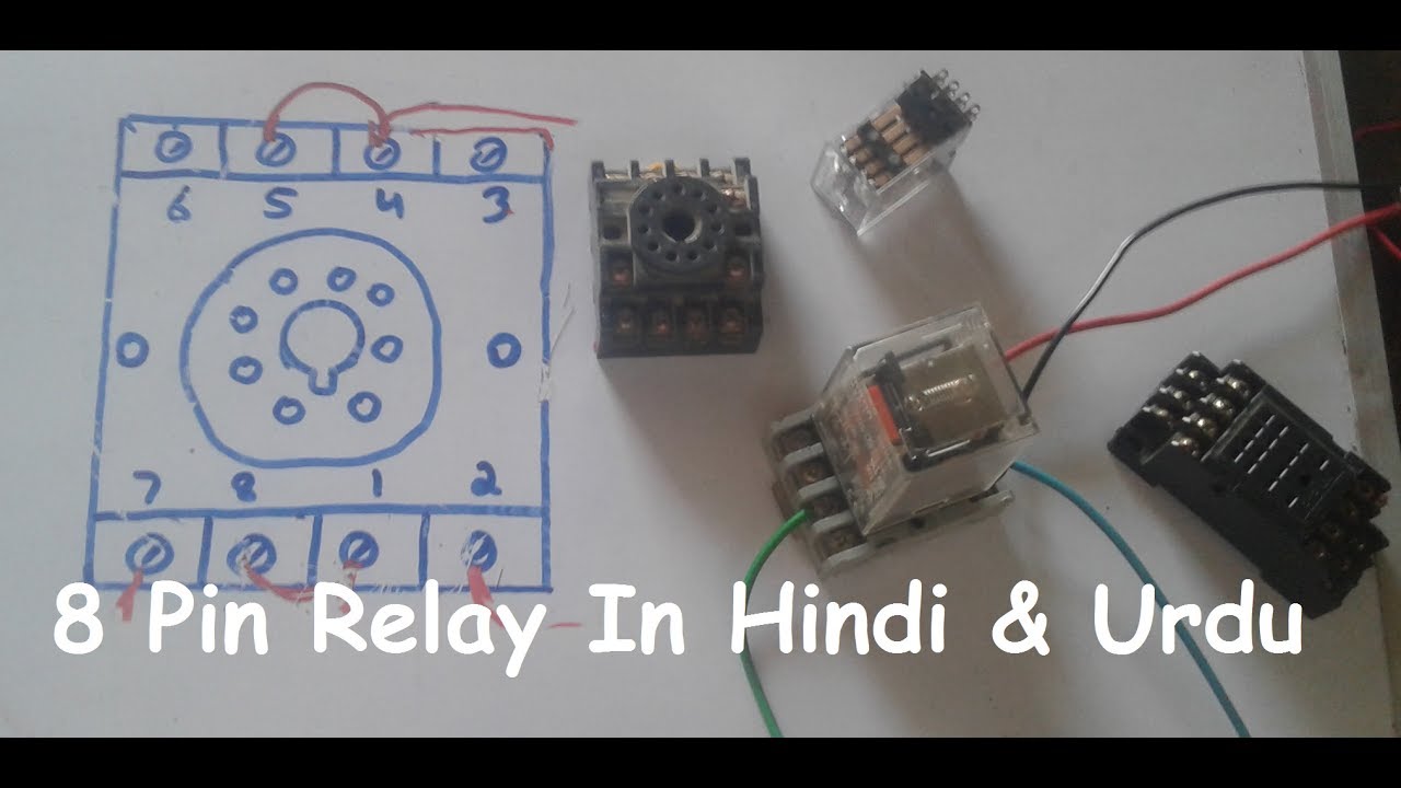
Omron mks2pin wiring diagram. Check coil polarity when wiring led indicator and diode models. This mk s series relay has dpdt agsnin contacts with standard led mechanical indicator and lockable test button. Mks2pin 2 datasheethtml 8 page omron electronics llc. 5 mk s dimensions unit. The mks2pin dc24 is a general purpose relay with dc coil and latching lever. Exceptionally reliable general purpose relay.
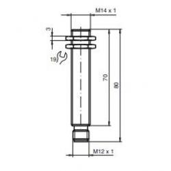
Nameplate provided on models with latching lever. Zoom in zoom out 8 10 page. Built in mechanical indicator enables checking contact operation. 12 volt relay wiring diagram 12 volt relay wiring diagram scribd relay wiring diagram used for accessories in a 12volt system a relay is typically used to control a ponent that draws high amperage the relay relay diagrams quick reference the12volt how to wire relays and relay diagrams a quick reference of dozens of automotive relay. Safety precautions safety precautions for correct use. Mm models without latching lever models with latching lever sockets see below for socket dimensions.
In order to provide the same easy testing as our other relay families the mk s is equipped with a lockable test button offering the same function. Two modes can be used to check circuits for models with latching lever. Omron mk2p i wiring diagram wiring diagram is a simplified enjoyable pictorial representation of an electrical circuit. Mks2pidc mks2pi dc b. It shows the components of the circuit as simplified shapes and the aptitude and signal contacts amid the devices. Recommend mounting mk s relay so that side with wiring diagram is facing down.
Use the surface mounting sockets ie finger protection models with e at the end of the model number.
Gallery of Omron Mks2pin Wiring Diagram