The wiring basics of connecting a tachometer rpm gauge to an outboard motor. Evinrude tachometer wiring best wiring library evinrude wiring harness diagram wiring diagram comes with several easy to adhere to wiring diagram guidelines.

Diagram Based Pro Comp Tach Wiring Completed Diagram Base
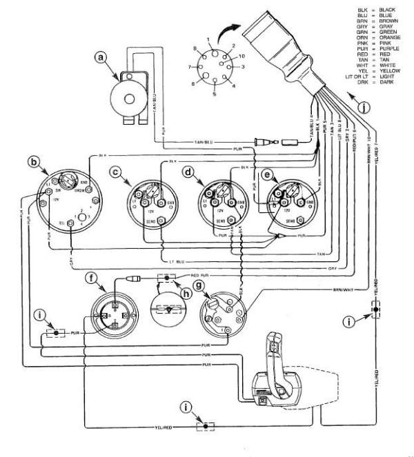
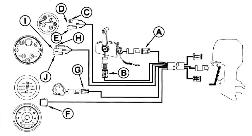
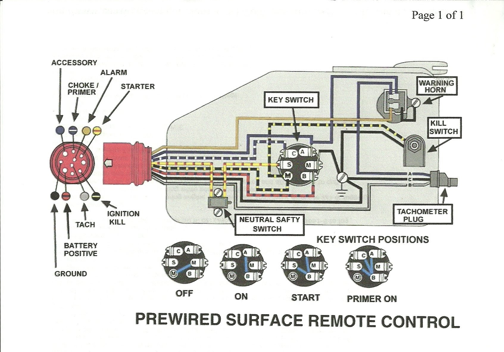
Omc tachometer wiring diagram. Image result for 70 hp johnson wiring to tachometer etc diagram rh pinterest com 70 hp johnson outboard 8 wires wiring diagram i bought a used 70 hp johnson outboard for my boat and had remove the gray wire from the tachometer. Its meant to help all the typical consumer in building a proper method. Wiring diagram 35 force wiring hp johnson outboard wiring image result for 70 hp johnson wiring to tachometer etc. Please verify your wiring before doing any work. Outboard wiring diagrams these diagrams are accurate to the best of our knowledge. 18 25 hp electric.
This flush mount alternator tachometer is designed for use on the following. Outboard engine wiring series links. Variety of yamaha outboard tachometer wiring diagram. A wiring diagram is a simplified standard photographic representation of an electric circuit. Omc sea drive models. However variations can exist such as between remote control and tiller models.
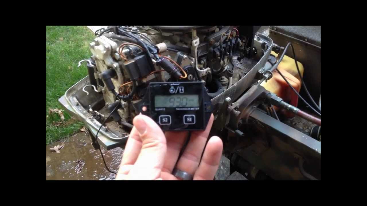
Non brp products with 20 pole alternators. 1996 evinrude 40hp parts used in this test. It reveals the elements of the circuit as simplified forms as well as the power and signal connections in between the tools. Johnson and evinrude outboards. 18 25 hp starter system thru 1972. Outboard motor control wiring part 1.
Gallery of Omc Tachometer Wiring Diagram