Please note that these instructions are the same for cat 6 cable and and other type of 4 twisted pair network cable. It simply reverses some of the pins so that the output on one computer is being sent to the input of another.
Ethernet Crossover Cable Images Ethernet Crossover Cable
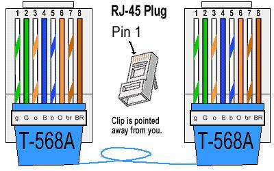
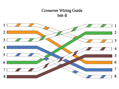
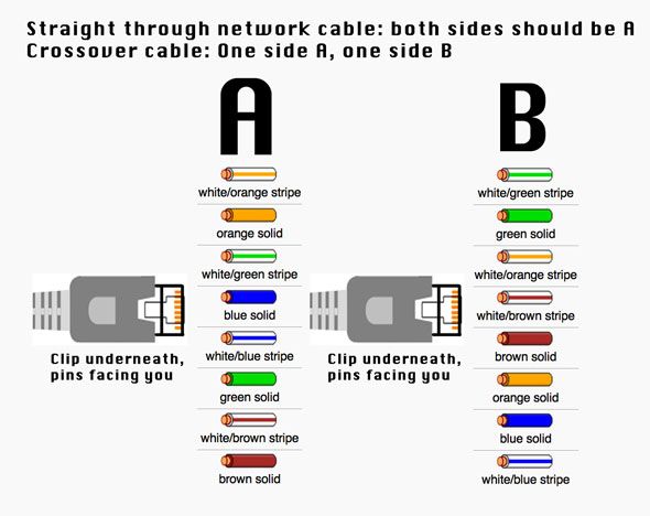
Network crossover cable wiring diagram. Pin no wire color transmittingreceiving. However a crossover cable can be used to connect two devices directly without the need for a router in the middle. The following ethernet crossover cable diagram represents the wiring for a cat5 and cat5e crossover cable. One end uses the t568a wiring standard and the other end uses the t568b wiring standard. Remember that pin 1 is on the left hand side of the rj45 connector with the clip at the rear. Another way of remembering the color coding is to simply switch the green set of wires in place with the orange set of wires.
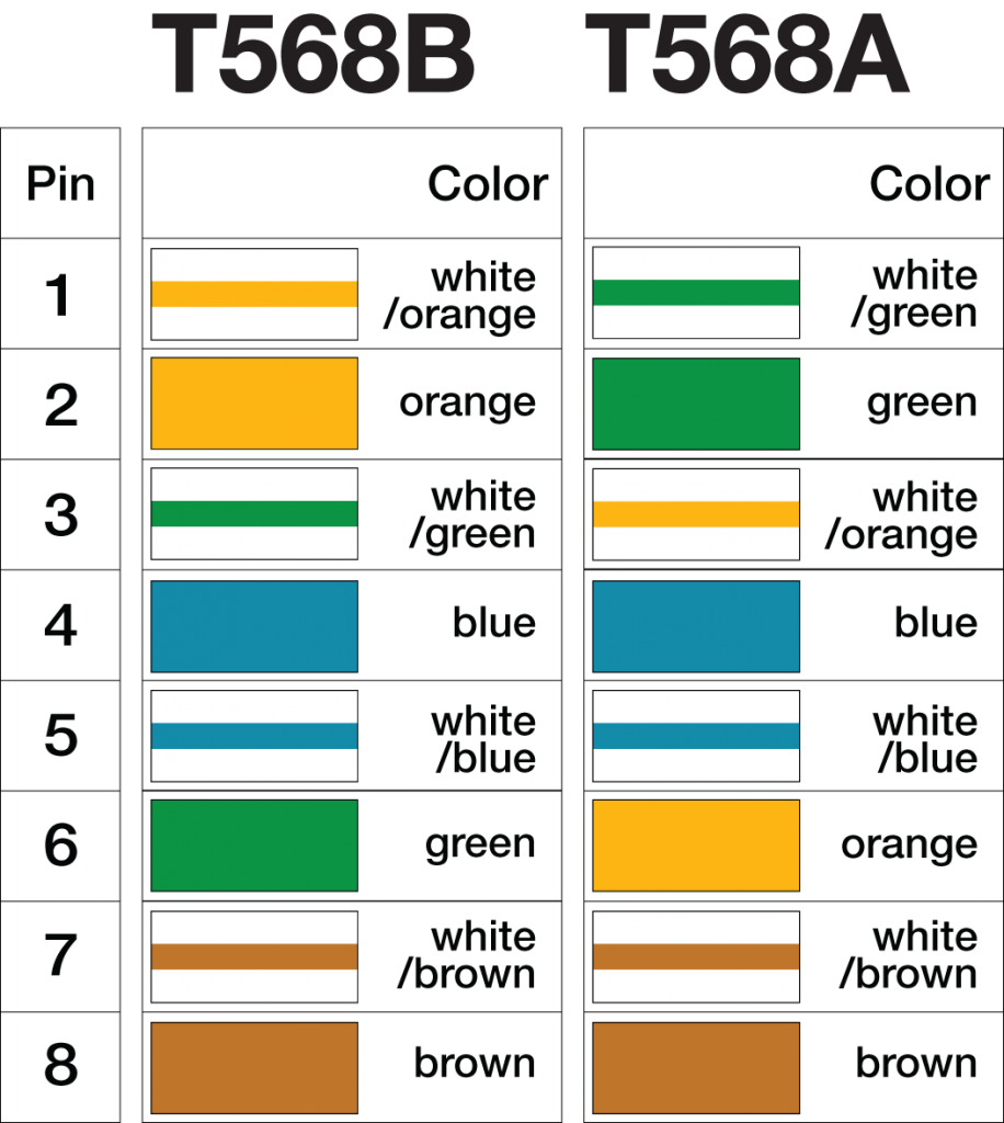
Click to check the right one for you or print as reference. A crossover ethernet cable is a type of ethernet cable used to connect computing devices together directly. Crossover cable color code tia 568b. Rj45 ethernet cable pinout. Following table illustrates tia 568b color coding scheme which is applied on left end of cable in crossover cable wiring diagram. In some network applications the equipment is so close together that a crossover.
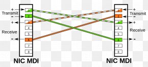
This effectively crosses over the connections between transmit and receive pins. Like you want to connect two routers or two pcs. T1e1j1 rj48 cable diagram the following illustration provides the wiring connections for straight or crossover cables. Pin 8 brown wire. Click to find view print and more. Crossover ethernet cables are used to connect two devices of the same type together.
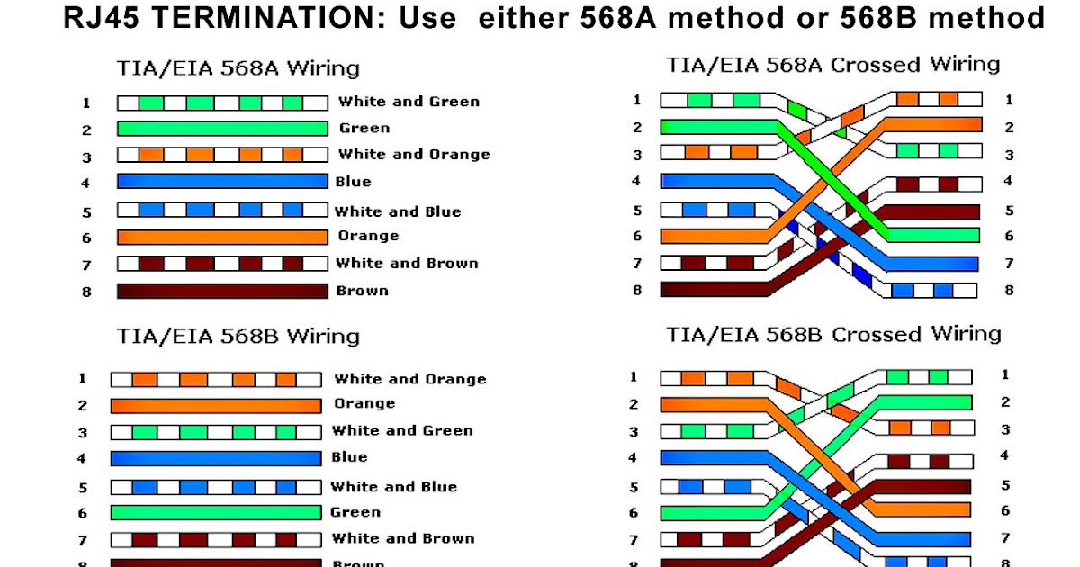
Some of us have fond memories of using a cross over cable to play multiplayer games before the internet was a thing. Rj 45 crossover ethernet cable a good way of remembering how to wire a crossover ethernet cable is to wire one end using the t 568a standard and the other end using the t 568b standard. Crossover cable wiring pinout and diagram a crossover cablealso known as xover cable follows the t568a schemeat one end and t568b schemeat the other. Cat 5 wiring diagram crossover cable diagram. The crossover cable diagram shows the transfer and receive wires are crossed this allows the computers to talk directly to each others. The complete ethernet pinout cable wiring reference with wiring step by step guide.
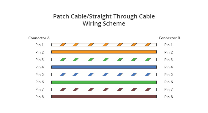
Rj45 pinout diagram shows wiring for standard t568b t568a and crossover cable. Remember the rj45 wiring order. Unlike straight through cable the rj45 crossover cable uses two different wiring standards. In normal setups youll use a straight through cable where the wires are the same on each side. Two for the transmit signal and two for the receive. This cat5 wiring diagram and crossover cable diagram will teach an installer how to correctly assemble a cat 5 cable with rj45 connectors for regular network cables as well as crossover cables.
Gallery of Network Crossover Cable Wiring Diagram