It shows the way the electrical wires are interconnected and will also show where fixtures and components could be. High voltage remove primary power before servicing the sign or transformer in any way.
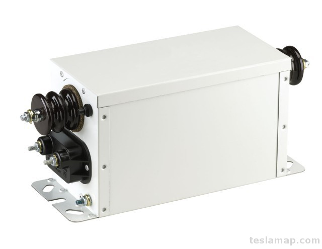
Rtftechnologies Neon Sign Transformer
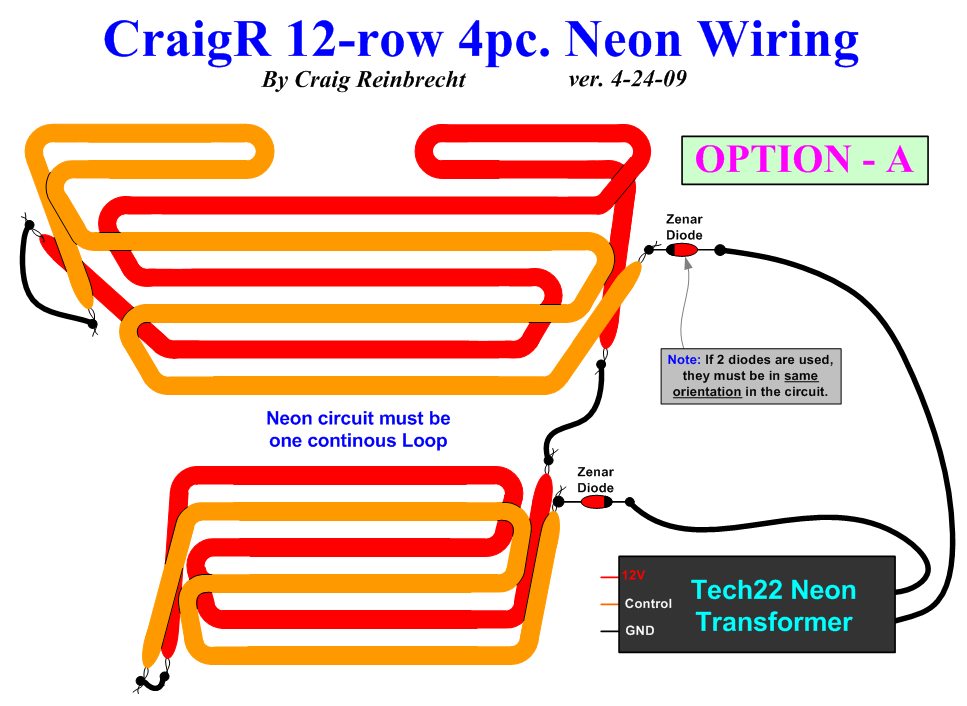
Neon transformer wiring diagram. The installation and wiring process for a neon sign is standard and will work regardless of brand or type neon sign. A wiring diagram is a simplified standard pictorial representation of an. Neon transformer installation guide this neon transformer is outdoor type 2 non weatherproof installing the france p5g 2ue series neon transformers see installation diagrams on reverse. Assortment of neon sign transformer wiring diagram. Neon sign transformer wiring diagram download. The next article in this series provides a review of the secondary conductor installations and wiring methods from the transformer output hubs to the tubing electrodes.
The neon industry and its transformer manufacturers have advocated alternative methods of wiring these runs of glass tubing. Neon sign transformer wiring diagram what is a wiring diagram. Wiring up neon light workshop sign bbkp duration. Savvas papasavva 27624 views. Output 2 from neon transformer goes to neon tube. How to wire a neon sign transformer duration.
The important part is selecting the correct transformer the size and capacity of which is based on the voltage requirements of the neon sign. Id suggest you use thhn outdoor rated machine tool grade wire and a. It reveals the components of the circuit as simplified shapes and also the power as well as signal connections between the gadgets. If you dont use the right transformer your neon sign could fail to operate properly. A wiring diagram is a straightforward visual representation in the physical connections and physical layout associated with an electrical system or circuit. As an example a 15000 volt 30 ma transformer may draw 375 amps at 120 volts or about 450 volt amperes as shown in most neon transformer catalogs.
Posted on may 7 2018 august 9 2018 by headcontrolsystem. Secondary circuit ground fault protected scgfp transformers will not. This practice minimizes the length of gto in conduit between the neon transformer hv outputs and the closest pair of electrodes to be. July 15 2019 by larry a. Neon sign transformer wiring diagram lovely sciencemadness. Ie clock motor and transformer input are wired in parallel in case its not labeled neon transformer input is low resistance neon transformer output is higher resistance polarity to and from transformer doesnt matter.
Transformer checklist diagram from neon lighting page 230. In neon transformer applications the volt amperes must be multipliedby the power factor tocompute the input power. The methods applied are called midpoint and virtual mid point wiring. The retro gamer 2308 views. Wellborn variety of neon sign transformer wiring diagram. Electric water heaters but not for neon transformers.
Electrical inspections lighting and control neon septemberoctober 2003. A wiring diagram is a streamlined standard pictorial depiction of an electric circuit.
Gallery of Neon Transformer Wiring Diagram


%20-%2024Sep13.jpg)