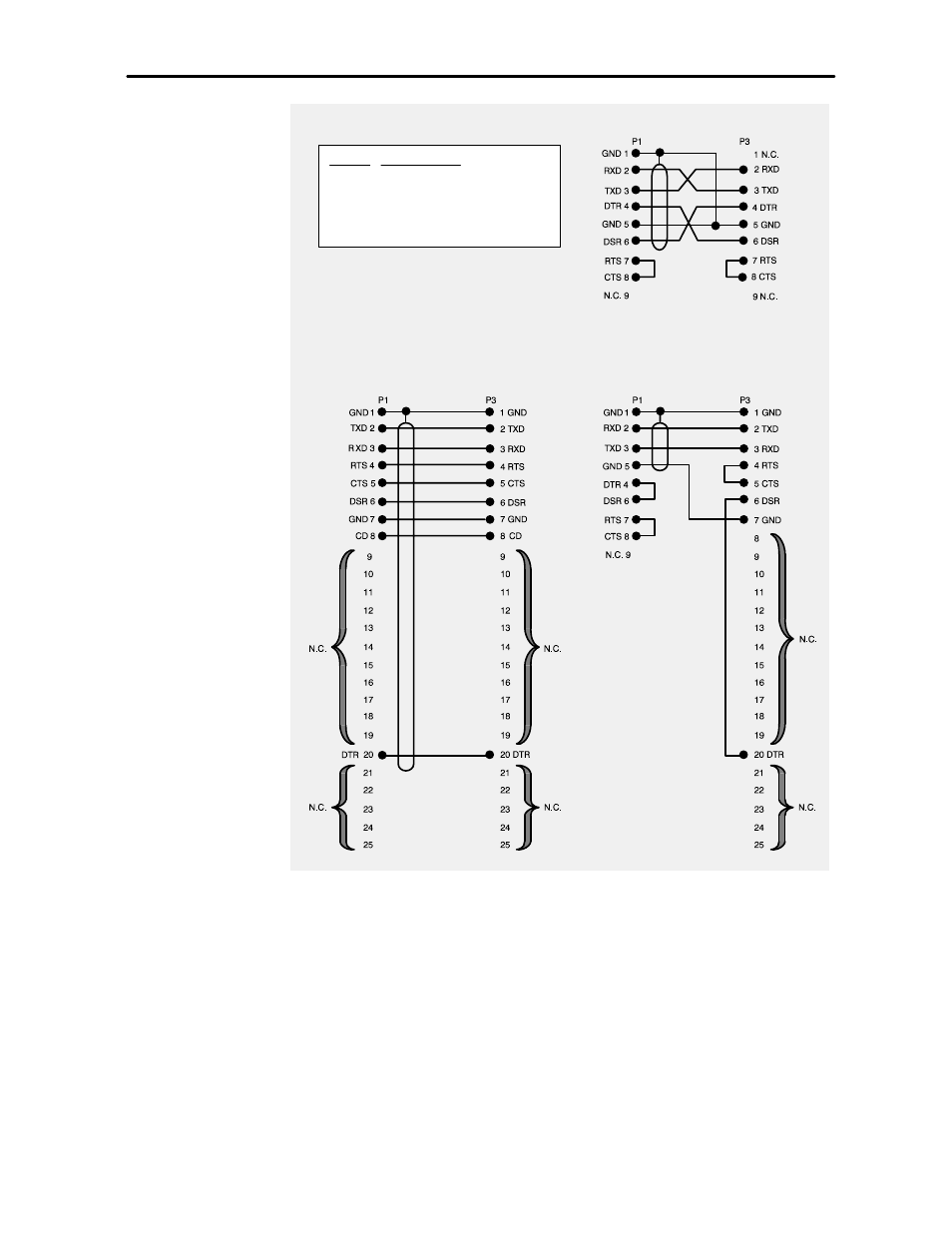
Please follow electrical regulations and recommendations in selecting the wire size and type. Operator and installation manual remote network monitoring powercommand iwatch 100 english 12 2007 9000545 issue 3.

Eg 2522 Modbus Wiring Diagram Find Latest Part Diagram
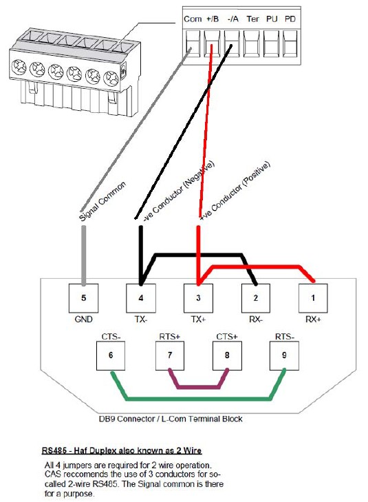
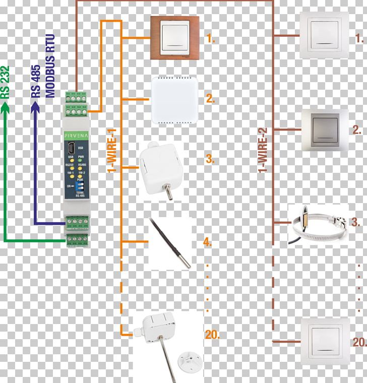
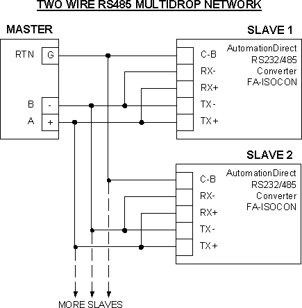
Modbus wiring diagram. 5 modbus rtu connection diagram rs 485 connection name modbus ziehl eiatia 485 wire d0 b b a wire d1 a a b. Cable termination rs485modbus rtu line bias overview. A wiring diagram is a simplified conventional photographic representation of an electrical circuit. A wiring diagram usually gives information about the relative setting as well as arrangement of gadgets as well as terminals on the gadgets to assist in structure or servicing the gadget. Primary applications for babel buster sp are serial to ethernet conversion of modbus devices and snmp access to serial or ethernet modbus devices. Tiaeia 485 rs485 two wire interface is the most common.
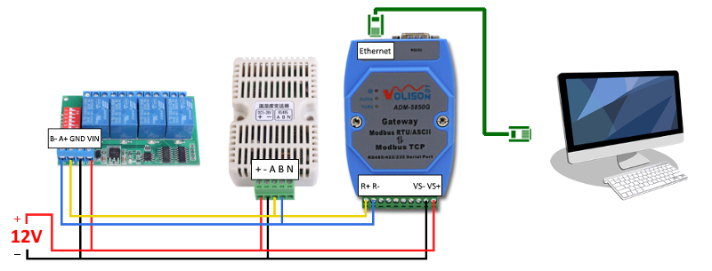
The modbus tcp interface can operate as master and slave at the same time. With multiple options available belden has a flexible and dependable modbus solution for key applications. 1 von 10 modbus tcpip tcp port. Modbus rs485 wiring diagram wiring wiring diagram collection a beginner s overview of circuit diagrams a very first look at a circuit representation might be complicated yet if you could read a subway map you can review schematics. At the physical level modbus over serial line systems may use different physical interfaces rs485 rs232. The end resistance must be used only at the ends of the main cable.
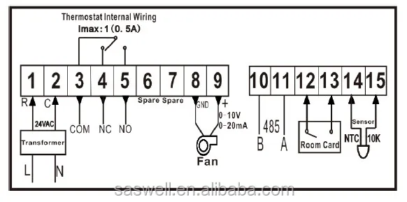
You can even use babel buster as an alarm notification device. Ensure that the wires are making good contact with the. Go back to modbus rs485 cabling rules 8. Assortment of modbus rtu wiring diagram. The modbus rtu port can operate as master or slave. Wiring diagram 2 front panel terminals follow these instructions accordingly otherwise damage may occur to the device.
95 amr130 3 61 4 21 30 30 35 46 79 11 1 2 6. Modbus protocol description drawing no. Modbus has been a standard for interfacing remote io and plcs into the process dlc system for over 20 years allowing most legacy control systems to interface easily with modbus. Several cables and wiring methods are referenced by installers when deploying modbus communications networks. As an add on option rs485 four wire interface may also be implemented. Engineers at deck monitoring have reviewed information from many sources to create the following recommendations for a standard and robust wiring method.
In order to avoid signal reflections a 120 ohm termination resistance must be fitted on each end of the main cable. It reveals the parts of the circuit as streamlined shapes and the power as well as signal connections in between the devices.
Gallery of Modbus Wiring Diagram