The charts on this page provide specs for testing your mercury mariner outboard ignition components. So stator has just cooled off ive successfully got 99 of the black plastic off it.
Outboard Spares Blog Troubleshooting 2 Stroke Ignition Problems
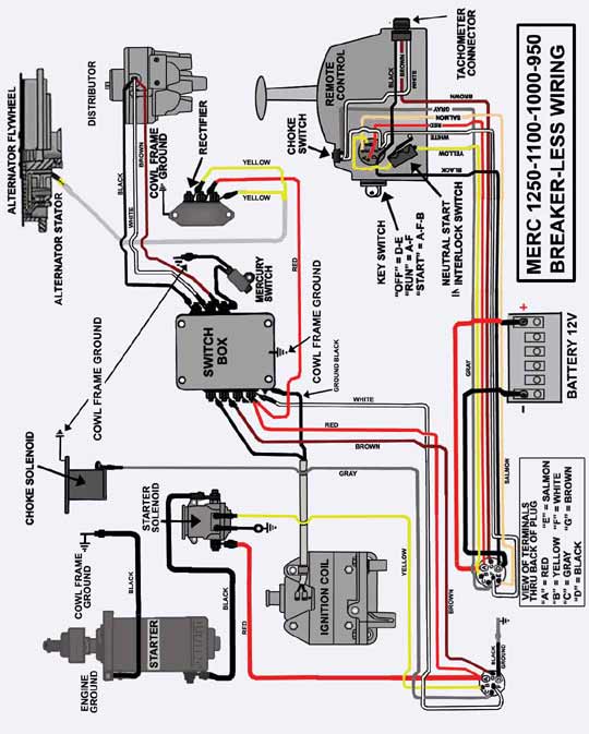
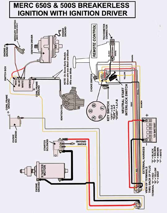
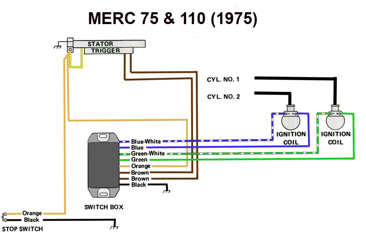
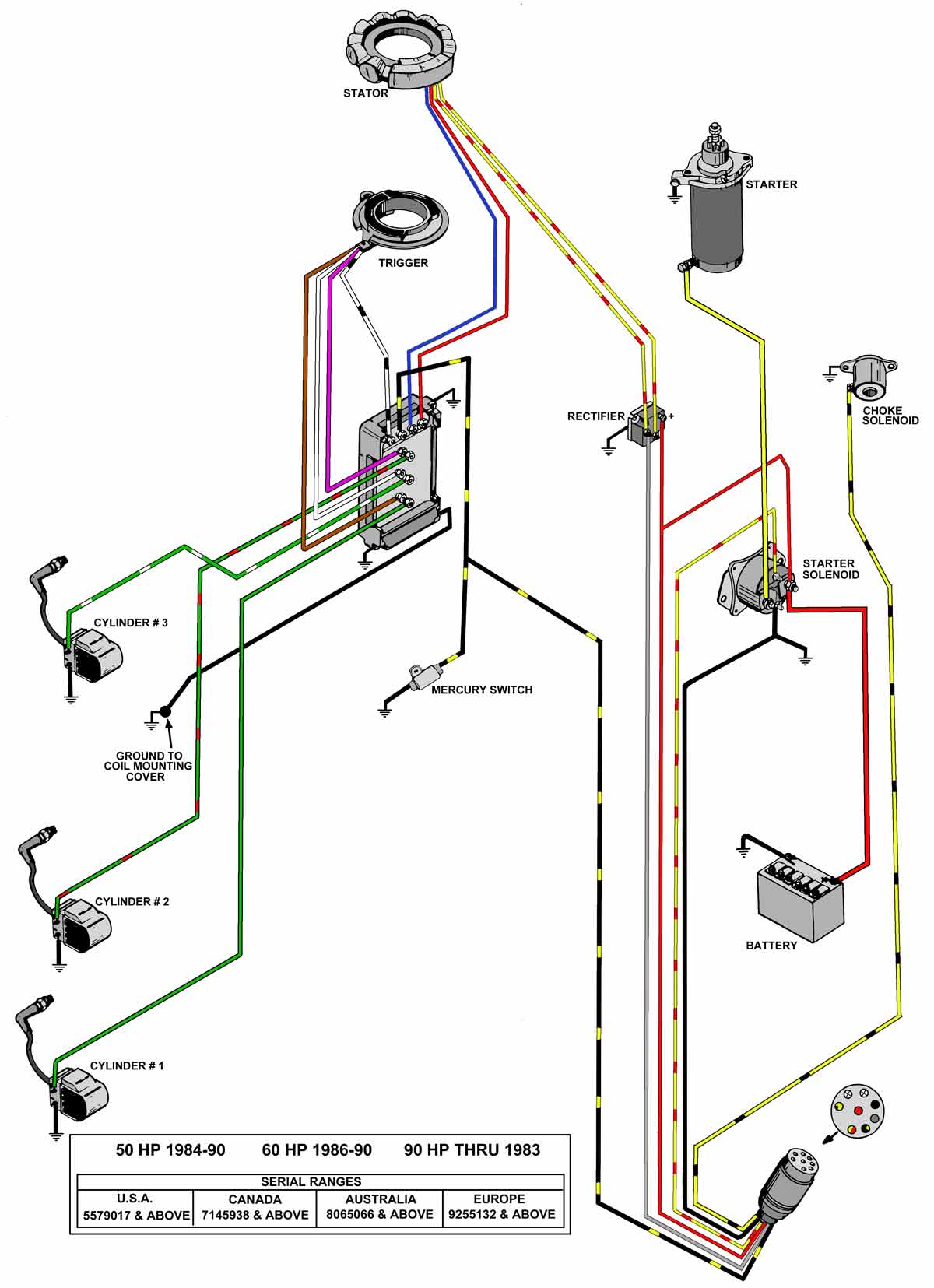
Mercury stator wiring diagram. May 19 2019 by larry a. If this stator is to be used as a replacement for the red mercury stator series connect all wires as they were originally from the factory. A wiring diagram is a streamlined traditional pictorial depiction of an electrical circuit. Trigger ohms trigger dva trigger wire to wire. Most models also have black white only. And stop at 8 then they are extended to reach.
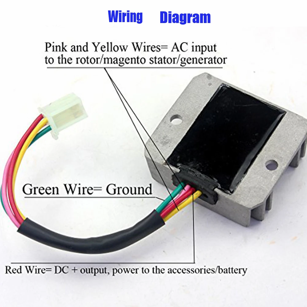
The linked images are printable but may print across more than 1 page in order to be legible. A wiring diagram is a streamlined traditional photographic depiction of an electric circuit. Tags for this thread. Outboard ignition parts for mercury mariner outboard motors. These codes apply to later model motors approximately early 80s to present. 13296 i take it the yellow think wires are the charging voltage.
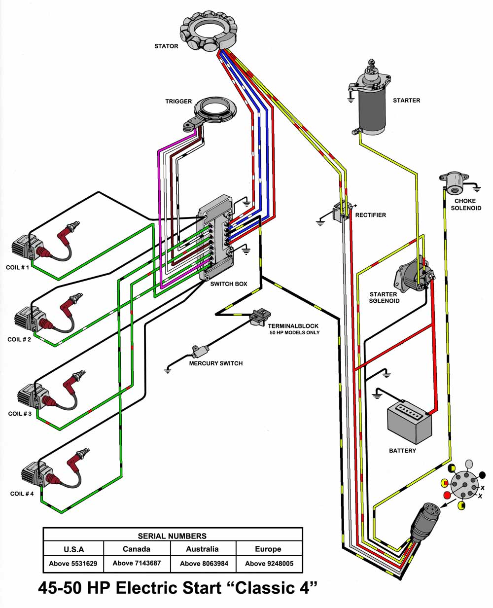
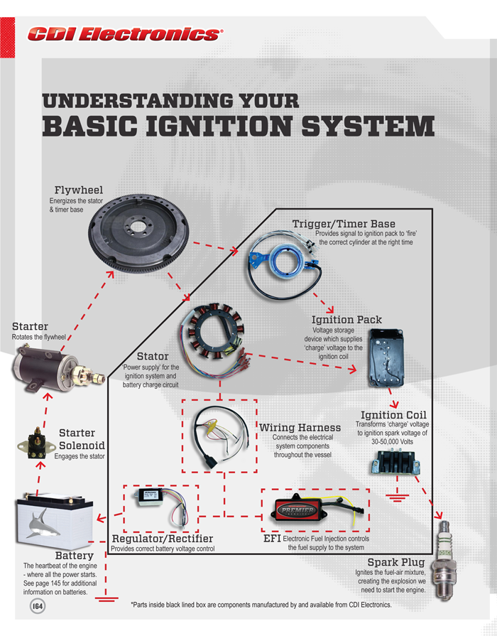
See note below for 3 cylinder engines. I need a wiring diagram for mercury red stator. Wellborn collection of wiring diagram for mercury outboard motor. Stator wire to wire. It reveals the parts of the circuit as simplified shapes as well as the power and also signal connections between the devices. Power pack stator timerbase regulator.
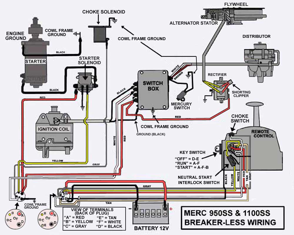
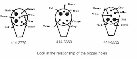
By forced in forum technical discussion replies. Can someone help me grasp how the windings work yes going to attempt to do this myself. Wiring diagram red stator. Ignition coil ohms primary output. Mercury outboard rectifier wiring diagram mercury outboard rectifier wiring diagram every electric structure is made up of various unique pieces. Wiring color codes here is a listing of common color codes for mercury and mariner us made outboard motors.
A black ground wire and either a single or two blue wires for connection to the switch box. If not the structure will not work as it should be. Collection of mercury outboard wiring diagram. The blue wire broke off and ground wire but here is a pic of it. It reveals the parts of the circuit as streamlined forms and the power and signal links in between the tools. Triggers usually never go bad on these mercury motors so at first i skipped the dva check on the trigger but went back on a lark just.
By forced in forum posting questions and suggestions replies. Each component ought to be set and linked to different parts in particular manner. They start winding at 1. Dva stator output stator output withing normal limits.
Gallery of Mercury Stator Wiring Diagram
%2C445%2C291%2C400%2C400%2Carial%2C12%2C4%2C0%2C0%2C5_SCLZZZZZZZ_.jpg)
.jpg)