The cold water combination valve can be connected to a maximum mains supply pressure of 16 mpa 16 bar. Page 5 the megaflo has an operating pressure of 3 bar which is controlled by the cold water com bination valve.

Wall Receptacle Wiring Diagram Timorer 2011 Rmnddesign Nl
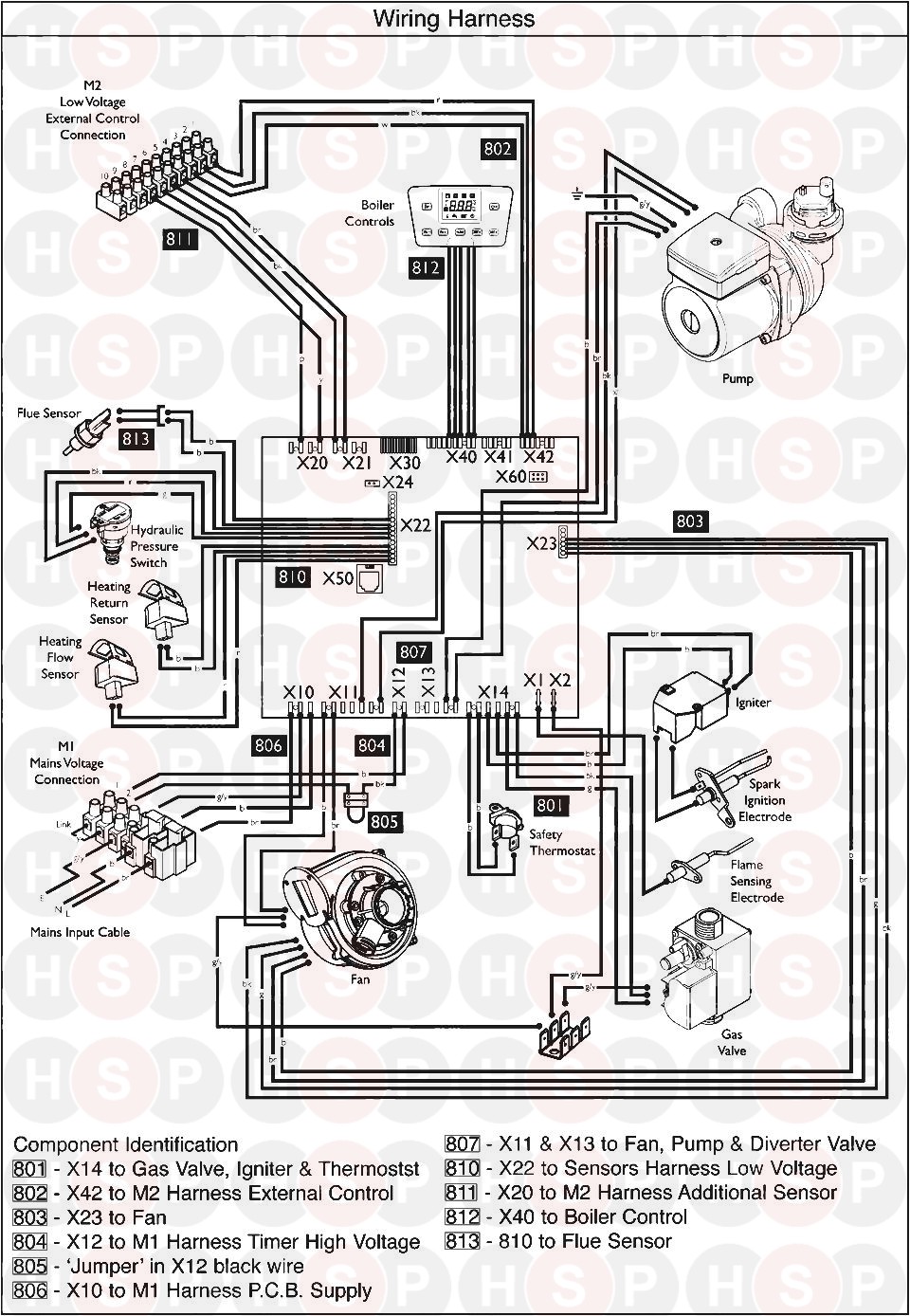
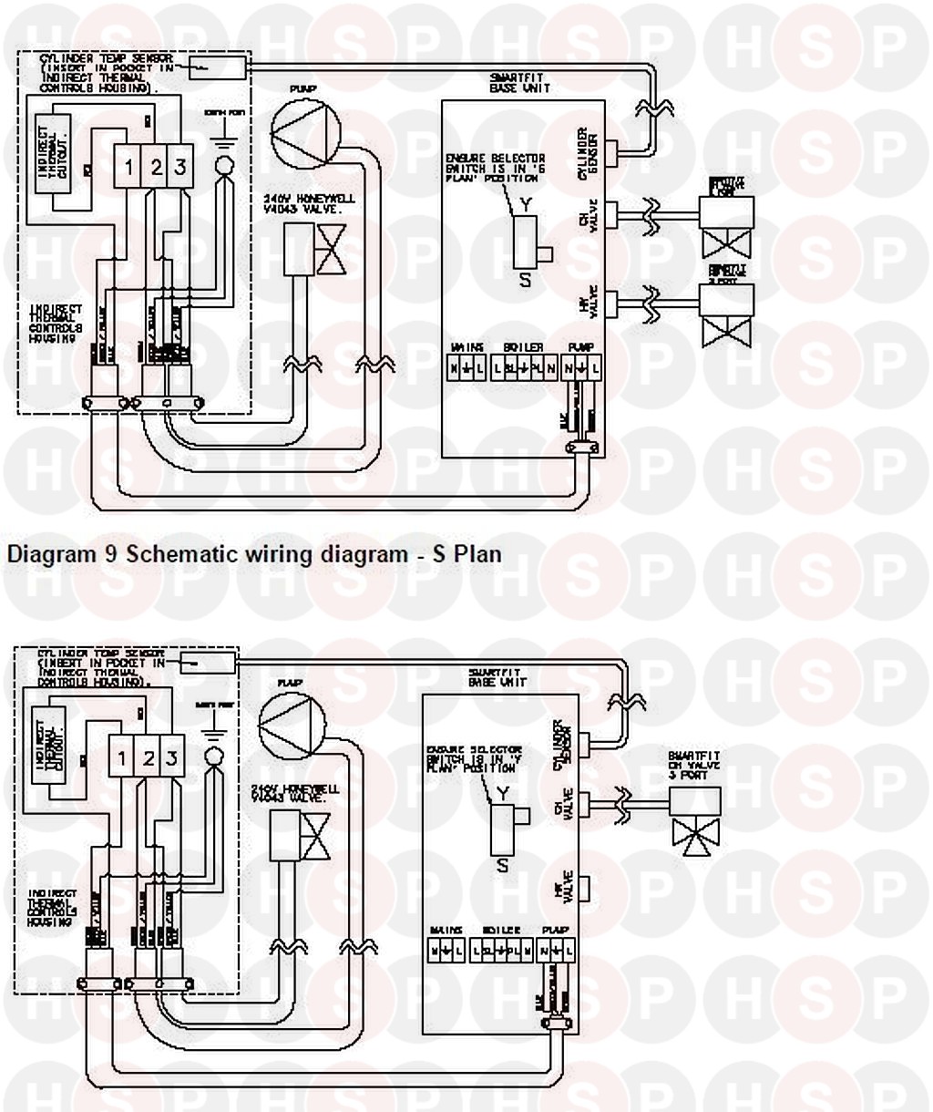
Megaflo wiring diagram. 22 for details. Megaflo eco plus product guide megaflo eco plus unvented indirect hot water cylinders 800l 1000l. Schematic wiring diagram 3 port mid position system 33 electrical diagrams 8 unvented hot water cylinder figure 5. Spare parts3 11 general 3 12 symbols used 3 13 abbreviations 3 14 liabilities 3 2. A press the to switch to switch to the settings view. Lokkars daisy new member.
B release for more than 2 seconds. 13a double pole isolating switch which is fed from the cu using 15mm 3 core hofr. The leds show the current setting for2 seconds. Safety 4 21 general safety warnings 4 22 recommendations 4 23 specific safety instructions 4 3. Immersion head assembly step 1. The diagram opposite shows the current operation status.
Discussion in electricians talk started by lokkars daisy aug 13 2005. Megaflo eco unvented direct indirect hot water cylinders. Page 20 immersion heaters the megaflo eco indirect units are supplied with an immersion heater which can be used as an alternative heat source should the boiler supply need to be isolated from the megaflo eco unitthe immersion heater is located within the controls housing refer to sections wiring and operationsee p. To change the pump stting follow below. Page 17 heatrae sadia installation manual diagram and instructions for connecting the 3kw immersion heater in the tank use a fused. Megaflo eco systemfit.
Gallery of Megaflo Wiring Diagram