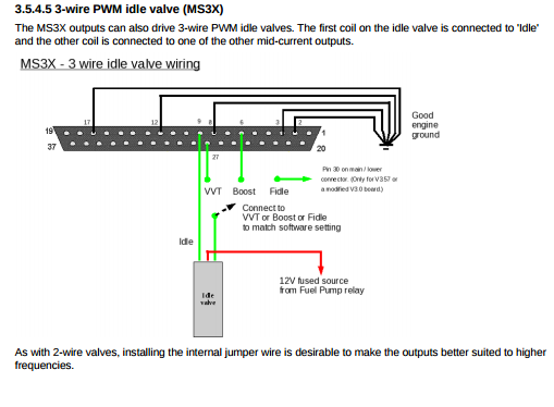
Efi 3 wire map sensor wiring diagram megamanual index external wiring schematic external wiring with a v main board some wiring considerations general guidelines for. Service manuals 1986 1993 30l 82l carbureted engines mefi 1 2 1993 1998 57l 82l electronic fuel injection mefi 1 2 1998 2001 57l 82l electronic fuel injection mefi 3 2001 2007 43l torque specs 50l 57l electronic fuel injection mefi 4 60l service manual mefi 4 81l electronic fuel injection mefi 4 mefi 4 tachometer failure 2007 2013 57l.
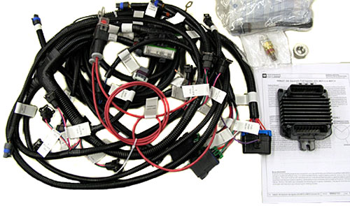
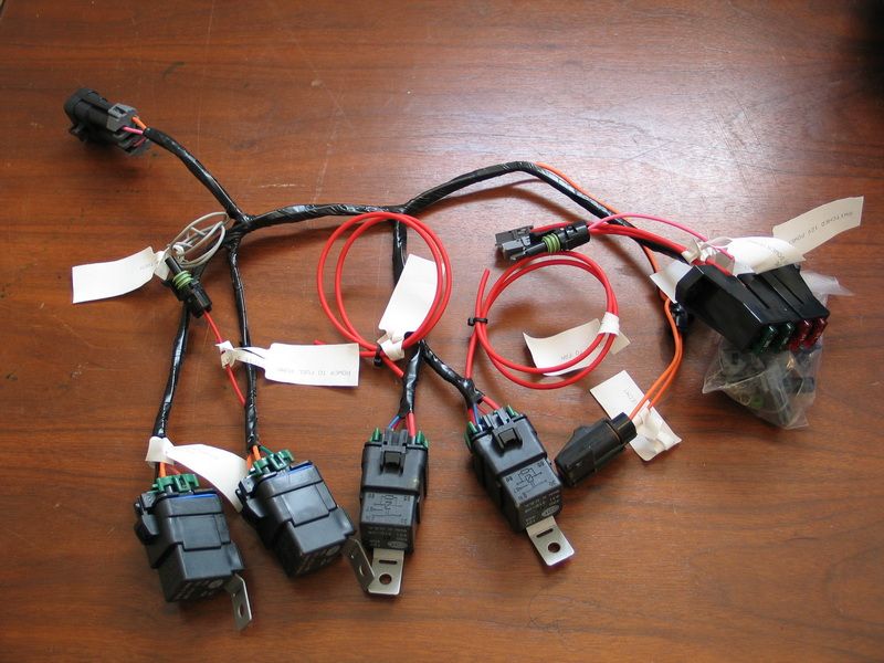
Mefi 4 Ecu And Wire Harness Kit Ram Jet 350
Mefi 4 wiring diagram. You should also understand what happens if a circuit becomes open shorted to ground. You should be familiar with wiring diagrams the meaning of voltage ohms amps and the basic theories of electricity. Cbm mefi stand alone ls ecotec wiring harnesss. The wiring schematics and circuit identifications are for the gm mefi originally equipped wiring harness. Cbm mefi mounting plate. With base tune or no tune.
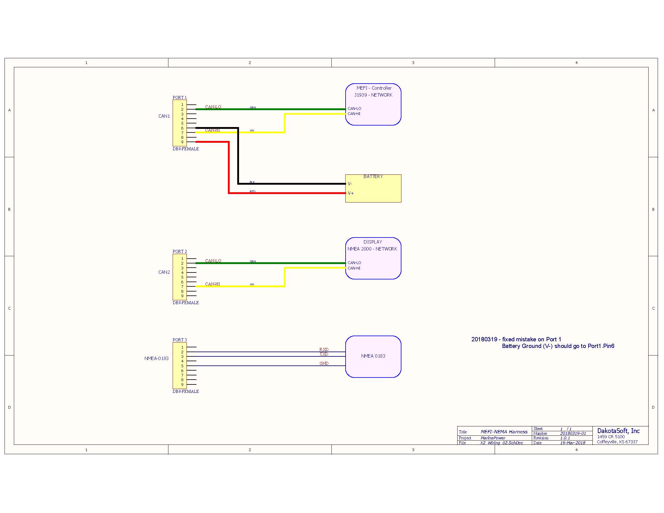
It is used in the assembly plant to receive information in checking that the engine is. Cbm motorsports online store. Heres a basic look at how the sensors in the speed density mefi 4 fuel injection work. You should be familiar with wiring diagrams the meaning of voltage ohms amps and the basic theories of electricity. Mefi 4 4a 4b electronic control modules mefi 4 4a 4b ecm s the ecm will ship blank and without a calibration. Wiring schematics distributor kit wiring diagram j1939 to nema2000 wiring mefi 4 mefi 4 engine controls schematic 43l 57l mefi 4 ecm circuit board layout 57 60 81l mefi 4 engine controls schematic 60l mefi 4 ecm engine wiring diagram 81l 57l wiring harness schematic 472605 mefi 5 mefi 5 engine controls schematic 60l mefi 5.
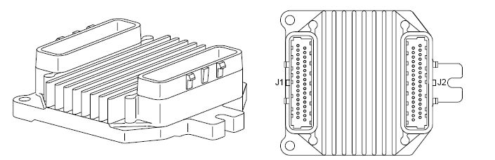
It is part of the mefi engine wiring harness and is a 10 pin connector which is electrically connected to the ecm. If available in our tune inventory we are happy to place a baseline tune in the computer at no additional cost. Mefi 4 pcm marine electronic fuel injection mefi section 1 general information contents. Cbm mefi electronic control modules for ls and ecotec versions 4 4a 4b and 5. The following diagram is a representation of the general inputs and outputs of the mefi 4 system. Engine load is primarily determined by sensing the current engine speed and reading the manifold pressure via the manifold absolute pressure map sensor this.
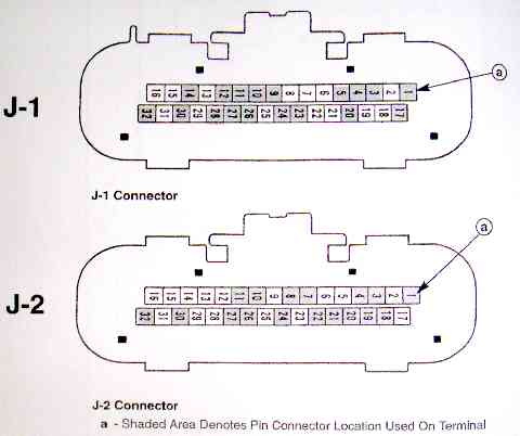
The diagnostic tables and voltages shown are prepared with the requirement that the system functioned correctly at the time of assembly and that there are no multiple failures. Mefi 4 pcm ecm connector pinout identifi cation 1 of 2 16 15 14 13 12 11 10 9 8 7 6 5 4 3 2 1 32 31 30 29 28 27 26 25 24 23 22 21 20 19 18 17 j 1 ecm 32 way connector ecm pin cktwire ckt wire circuit description number number color.
Gallery of Mefi 4 Wiring Diagram