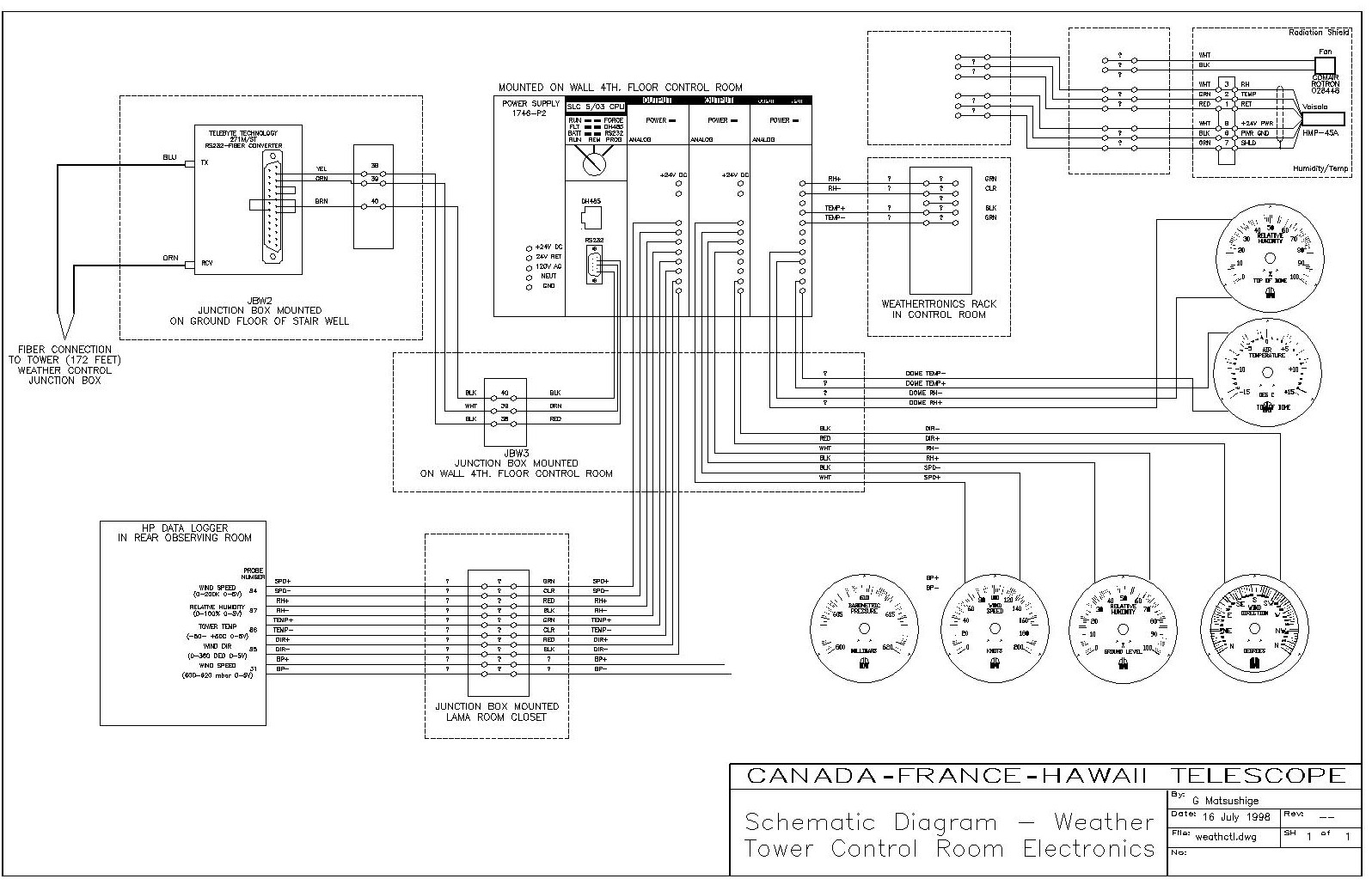
266219078 mcc panel wiring diagram and panel ga samplepdf free download as pdf file pdf text file txt or view presentation slides online. Motor control centers are simply physical groupings of combination starters in one assembly.
Electrical Control Panels For Beginners Oem Panels
Mcc panel wiring diagram pdf. Basics 8 aov elementary block diagram. Basics 13 valve limit switch legend. This drawing include the sample sld wiring panel general arrangement diagram. The model 6 mcc has the largest vertical wireway in the industry. Tiastar mcc identification guide. Scribd is the worlds largest social reading and publishing site.
Wiring diagram for bms ddc panel vnd592vxkglx. Basics 10 480 v pump schematic. Panel boards and wiring november 2019 100. They shall be used in lieu of distribution panels and separate starters in these locations. Tiastar mcc catalog and application guide. Tiastar mcc high density.
A combination starter is a single enclosure containing the motor starter fuses or circuit breaker and a device for disconnecting power. Tiastar mcc more than motors. Captive four bolt horizontal splice bars with self contained nuts and hardware make installation easy and reduce the possibility of splice bar loss. Basics 11 mov schematic with block included basics 12 12 208 vac panel diagram. Mcc panel wiring diagram and panel ga sample november 2019 265. Basics 6 72 kv 3 line diagram.
Design guidelines and standards mcc 1 basis of design this section applies to the design and installation of motor control centers mccs and motor control equipment. Wiring diagram book a1 15 b1 b2 16 18 b3 a2 b1 b3 15 supply voltage 16 18 l m h 2 levels b2 l1 f u 1 460 v f u 2 l2 l3 gnd h1 h3 h2 h4 f u 3 x1a f u 4 f u 5 x2a r power on optional x1 x2115 v 230 v h1 h3 h2 h4 optional connection electrostatically shielded transformer f u 6 off on m l1 l2 1 2 stop ol m start 3 start start fiber optic. The apparatus designed for this function is the motor control center mcc. Basics 5 480 v mcc 1 line. Bms riser diagram for hvac system december 2019 181. Only diagrams of the individual units are supplied.
Nema class ii interwiring offers the addition of interlocking and wiring between units as specifically described in overall control system diagrams supplied by the purchaser. Basics 7 416 kv 3 line diagram. Tiastar mcc expanding installation possibilities with additional network connectivity. Design criteria provide mccs in mechanical rooms and other multi motor locations. And maintenance without the need to remove the panels. Contact your allen bradley distributor or rockwell automation sales representative for pricing and.
Mcc panel wiring diagram and panel ga sample free download as pdf file pdf text file txt or view presentation slides online. Tiastar mcc rugged reliable and high performance. Tiastar mcc integrated drives. Basics 9 416 kv pump schematic. Home current explore explore all. A full depth vertical wireway maximizes the wire pulling area.
Gallery of Mcc Panel Wiring Diagram Pdf