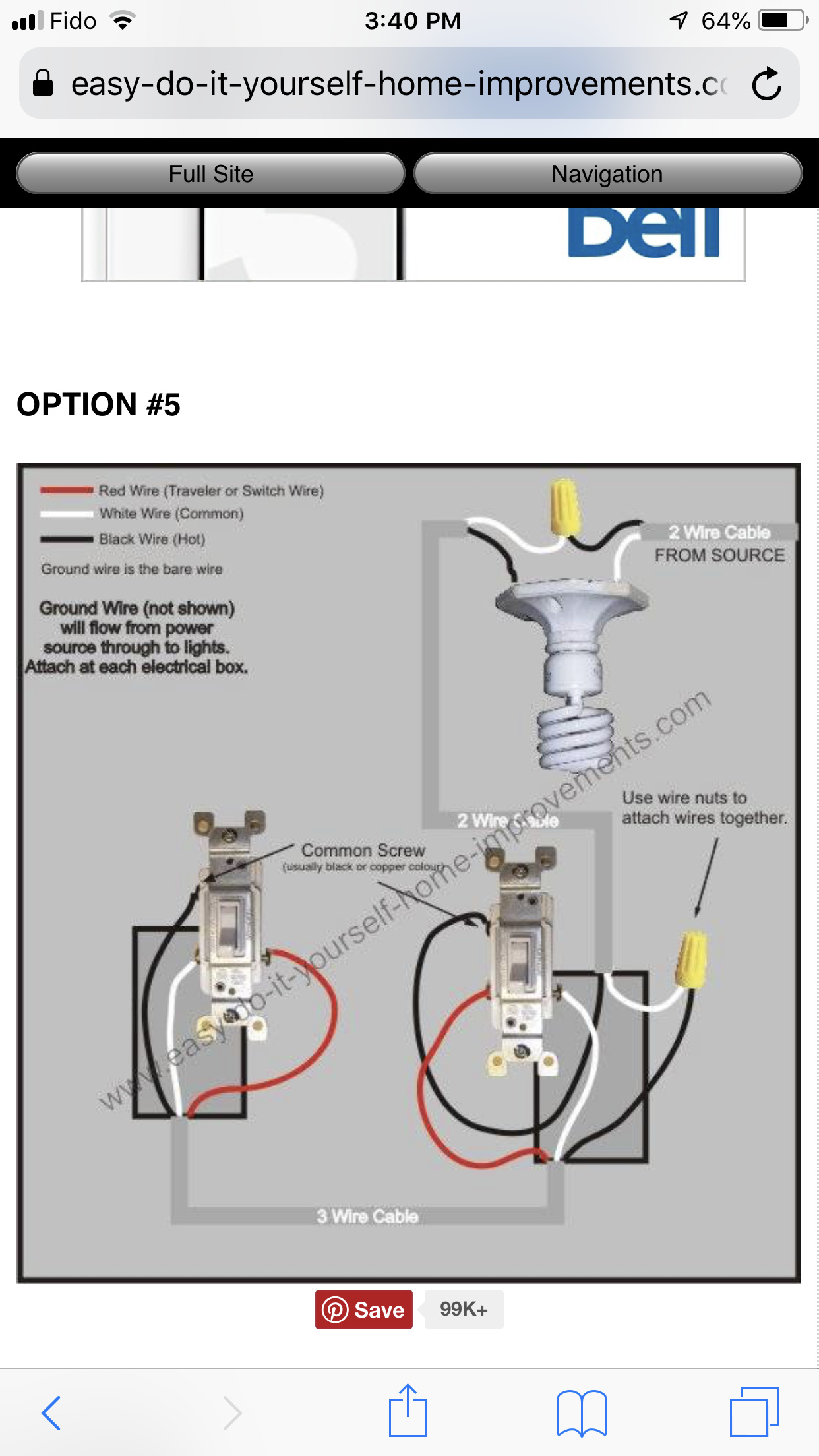
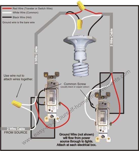
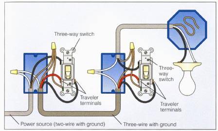
This might seem intimidating but it does not have to be. As you can see this picture corresponds to the diagram for the basic 3 way switch system above.

Amazon Ca Tp Link Kasa Smart Wi Fi Light Switch 3 Way 1
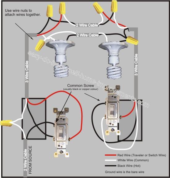
Kasa 3 way switch wiring diagram. Step 3remove existing faceplate and light switch then identify liveload neutral and ground lines. Pick the diagram that is most like the scenario you are in and see if you can wire your switch. No need to understand complex wiring just follow the step by step wiring process in the kasa smart app for a guided install of your dimmer light switch. 3 wire switch 4 wire switch tp link wiring instructions. The black hot wire connects to the far right switchs common terminal. Many variations of this basic theme are possible.
Grouping use grouping to combine your light switch with other kasa smart devices for seamless control with one single tap on your smartphone. 3 way switch wiring diagram. This wiring scenario is complex and hs210 has not been tested to work with this configuration. Take a closer look at a 3 way switch wiring diagram. Kasa smart wi fi light switch 3 way kit by tp link setup tutorial duration. Your kasa smart wi fi light switch 3 way comes with labels a faceplate and the necessary hardware for your convenience.
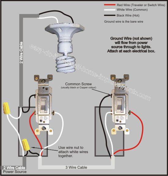
Step 4connect the smart switch wiring with the provided wire connectors as follows. In this diagram power enters the fixture box. For instance the 3 way switch schemes a b c above will allow a 4 way switch and box or any number of them to be interposed between the 3 way switch boxes. This 3 way light switch wiring diagram shows how to do the light switch wiring and the light when the power is coming to the light fixture. No need to understand complex wiring just follow the step by step wiring process in the kasa smart app for a guided installation. With these diagrams below it will take the guess work out of wiring.
A four way switch configuration is composed of two three way switches one on each end of the switching circuit and a special four way switch in between the two three way switches. Red and blue wires link traveler terminals of both switches. Connect each of the two black wires from the switch to the available live lines via the wire nut and wrap electrical tape around the wire nuts to make.
Gallery of Kasa 3 Way Switch Wiring Diagram