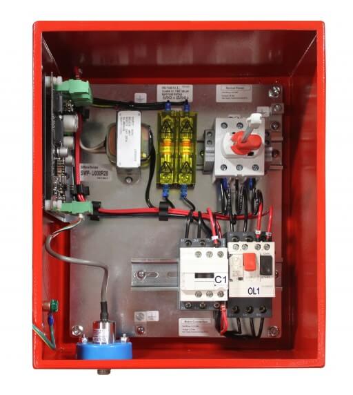
8 pjpc instructions jockey pump controllers single phase wiring diagram timer is optional and controller will function without it installed. Model jp3 jockey pump controller note.
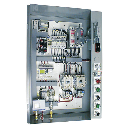
Transfer Pump Transfer Pump Control Diagram
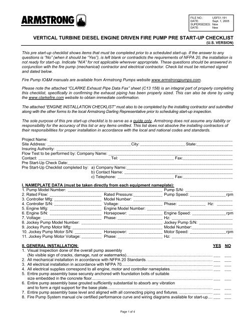
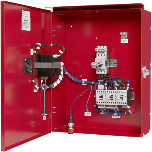
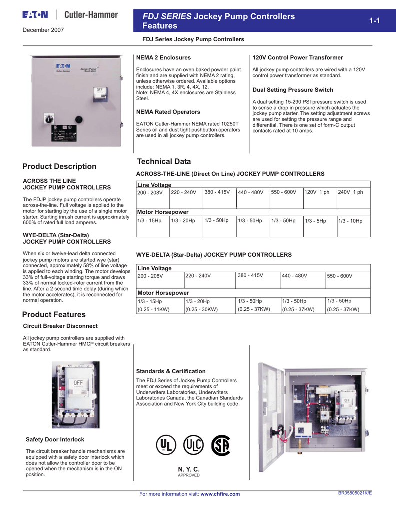
Jockey pump wiring diagram. Single phase variable speed jockey pump controller. Fire and jockey pump controller sensing lines mike trumbature with regard to fire pump wiring diagram image size 797 x 612 px and to view image details please click the image. You must not connect conductors supplying power for pressure maintenance jockey or make up pumps to the fire pump controller per sec. Three phase variable speed jockey pump controller. Pjpc instructions jockey pump controllers three phase wiring diagram timer is optional and controller will function without it installed. Here is a picture gallery about fire pump wiring diagram complete with the description of the image please find the image you need.
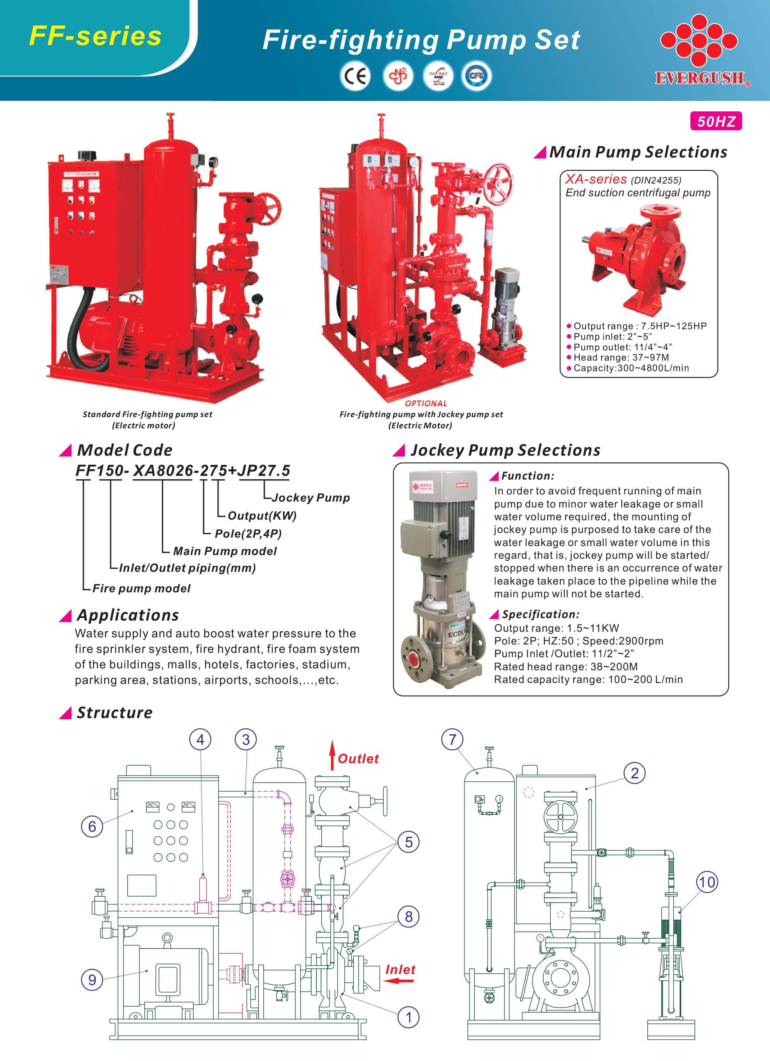
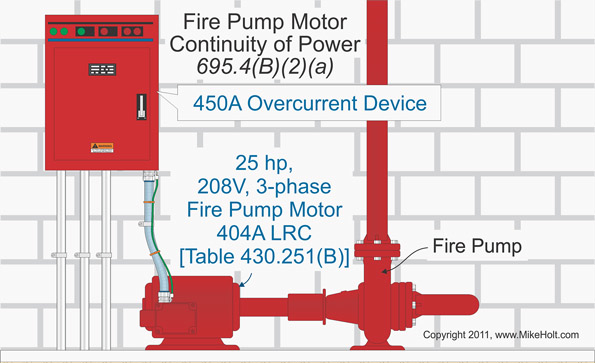
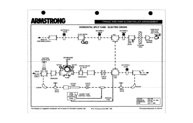
The above capture is an age old drawing covering sensing lines for a jockey pump and fire pump controller. A4 elapsed time meter time totalizer a5 motor run alarm contact a6 loss of power alarm contact a7 overload or short circuit alarm contact d12 ce mark cw externally mounted wetted parts. 7 344 in nfpa 20 and nec sec. You cannot use the fire pump controller as a junction box for wiring to supply other electrical equipment. Questions about the orifice checks in the sensing lines has come up quiet often. Jockey pump piping diagram a jockey pump is a small pump connected to a fire sprinkler system and is intended to maintain pressure in a fire protection piping.
Options chosen from this page are not electrically represented on the wiring schematics in this submittal package. Nema 2 variable speed jockey pump controller. Three phases variable speed pressure maintenance controller. Microsoft word iom pjpc jockey pump controller rev12 21 05.
Gallery of Jockey Pump Wiring Diagram