Iota i 32 wiring diagram 24102018 24102018 4 comments on iota i 32 wiring diagram the i from iota engineering is a ul listed fluorescent emergency ballast that allows the same fixture to be used for both normal and emergency operation. Wiring diagrams select an available diagram from the list below.

States Under State Of Emergency 2017 Iota Emergency Ballast
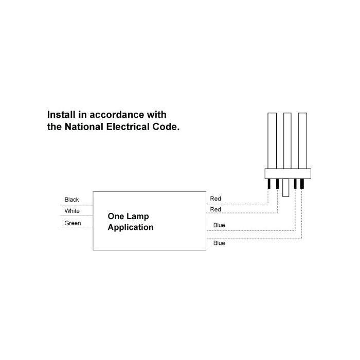
Iota i 32 emergency ballast wiring diagram. Wiring refer to the wiring diagrams on the back page for the appropriate wiring of lamps and ballast. Use the navigation window and select the emergency ballast for which the diagram is needed then scroll through the list of applications to find the. If you cannot find a diagram that matches your particular application contact customer service or call 1 800 866 iota with details regarding your application. It reveals the components of the circuit as simplified shapes as well as the power and signal links between the gadgets. The emergency ballast wiring guide. It reveals the parts of the circuit as streamlined forms and the power and signal connections in between the gadgets.
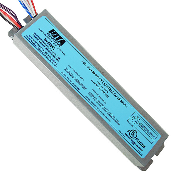
The i 32 fluorescent emergency ballast from iota engineering allows the same fixture to be used for both normal and emergency operation. Mount the i 32 in the ballast channel at least 12 away from the ac. For additional wiring diagrams consult customer service. In the event of a power failure the i 32 switches to the emergency mode and operates one of the existing lamps for 90 minutes. 4alling the threaded body test switch tbts inst. Collection of iota emergency ballast wiring diagram.
Wellborn collection of iota i320 emergency ballast wiring diagram. The i 32 may also be mounted on top of the fixture. The unit contains a battery charger and inverter circuit in a single can. Emergi lite iota fpdl7 13 fpdl10 42 fpdl18 26 fpdl10 42 d fps 80d fps 500 fps 540 fps 825 fps hl fpsi 24 fpsi 32. April 3 2019 by larry a. The i 232fluorescent emergency ballast from iota engineering allows the same fixture to be used for both normal and emergency operationin the event of a power failure the i 232switches to the emergency mode and operates twoof the existing lamps in parallelfor 90 minutesthe unit contains a battery charger and inverter circuit in a single can and can be mounted in the.
Mounting the i 32 remove the ballast channel cover. The i 32 can be used with most 2 4 t8 thru t12 and. The i 320 series acfluorescent emergency ballast from iota engineering allows the same fixture to be used for both normal and emergency operationin the event of a power failure the i 320switches to the emergency mode and operates oneof the existing lamps for 90 minutesthe unit contains a battery charger and inverter circuit in a single can and can be mounted in the. A wiring diagram is a streamlined traditional photographic depiction of an electric circuit. A wiring diagram is a streamlined conventional pictorial representation of an electrical circuit. The optional top mounting kit catalog no.
Number of lamps to be operated in emergency mode. Tmk 32 may be ordered separately from customer service. Install in accordance with the national electrical code and local regulations.
Gallery of Iota I 32 Emergency Ballast Wiring Diagram