Inkbird is a company which dedicates its passion in producing and marketing of intelligent home automation products. Ive got a type k thermocouple so its a 2 wire sensor.

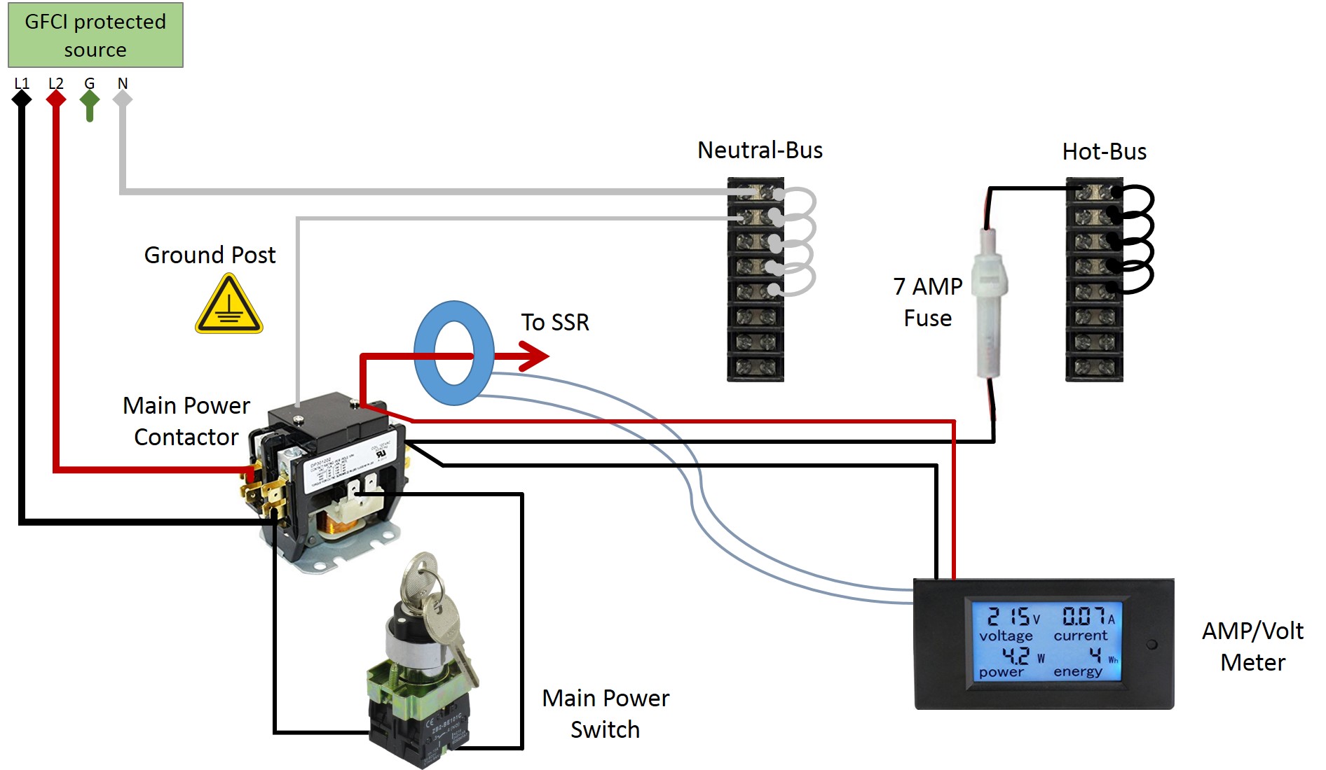
Wiring Diagram For Timer And Contactor
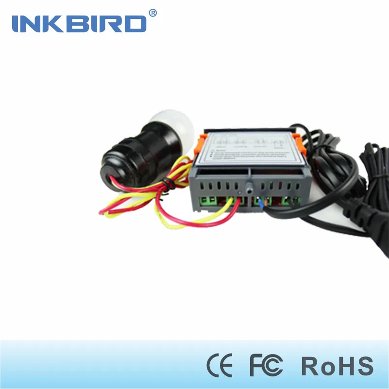
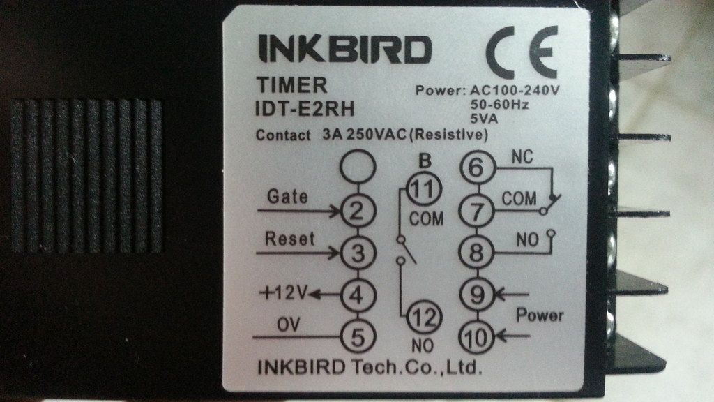
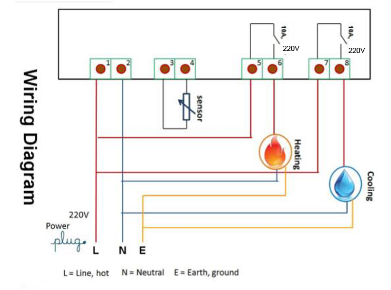
Inkbird timer wiring diagram. 9 and 10 terminals are for power connecting which its supply voltage should be match the item model. If youre using 2 wire sensor then it connects to terminals 3 and 4 and you put a short wire link between terminals 4 and 5. Here you can download our latest user manuals drivers and other supporting materials from inkbird support department. Din48x48mm digital counter 001s 99h99m time range with twin time set value individual output for ab perio. Barley and hops brewing 24385 views. Itc 100 controller pdf manual download.
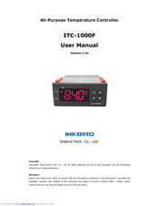
001s 99h99m time range with twin timer set value individualone shot or cycle time mode up or down modenpn and pnp input switchabletact switch for up or down set value easily operateoutput. Can it be set to activate when say the oven reaches temperature and the timer starts. Wiring my inkbird pid part 2 duration. Wiring diagram 2 wires sensor 3 wires sensor thermocouple output relay output voltage power connection. Some pt100 sensors are 2 wire and all thermocouples are 2 wire. View and download inkbird itc 100 user manual online.
When this timer is wired how exactly does it function. With excellent product quality and efficient technical and logistic service support inkbird has won good reputation worldwide. Edit i am using 220v 40amp 3 wire with ground. Building a 240 volt 20 amp pid controller step by step part 3 duration. A 2 wire pt100 sensor is likely to be slightly less accurate than a 3 wire version.
Gallery of Inkbird Timer Wiring Diagram