The wiring diagram on the opposite hand is particularly beneficial to an outside electrician. Its on page 1.

Does Anybody Know What Color Wires Are For The Iat Sensor For
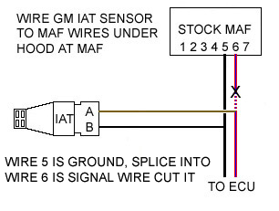
Iat sensor wiring diagram. Customer satisfaction is my goal. Find the black sensor ground wire and the redblue intake air temperature sensor wire going into the back of the maf plug and cut them. All you need is a 716 drill bit to create a hole in the box. I have sent wiring diagram. 22 shows the iat sensor mounted in the air box of an e60 545i. I need the location and wiring diagram for the iat sensor on a 2018 ford focus 20l answered by a verified ford mechanic we use cookies to give you the best possible experience on our website.
Gm open element intake air temp sensor wiring pigtail. I am doing the very best to helpshould you have any followup to this question please ask but be advised. Then a picture of the sensor and a location picture. Notice how every one of these installs involve placing the iat sensor directly in the path of incoming air for the best possible sampling. Sometimes wiring diagram may also refer to the architectural wiring program. Aug 11 this is a write up on how to wire in a gm iat intake air temp sensor in a 2g and logging it using dsmlink v3.
File links are now on your page. By continuing to use this site you consent to the use of cookies on your device as described in our cookie policy unless you have disabled them. Since you wired in the gm iat into. The simplest approach to read a home wiring diagram is to begin at the source or the major power supply. The wiring harness is routed around the air box to the maf sensor and it is connected and secured out of the way. The iat sensor can be installed on the lower half of the intake box right above the drain outlet.
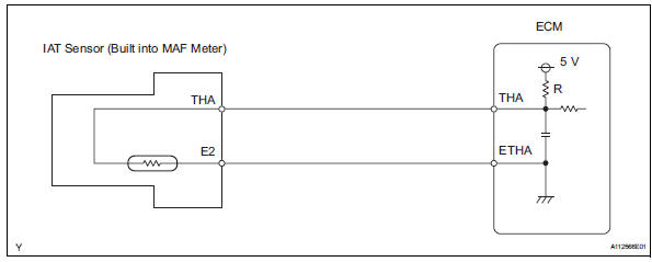
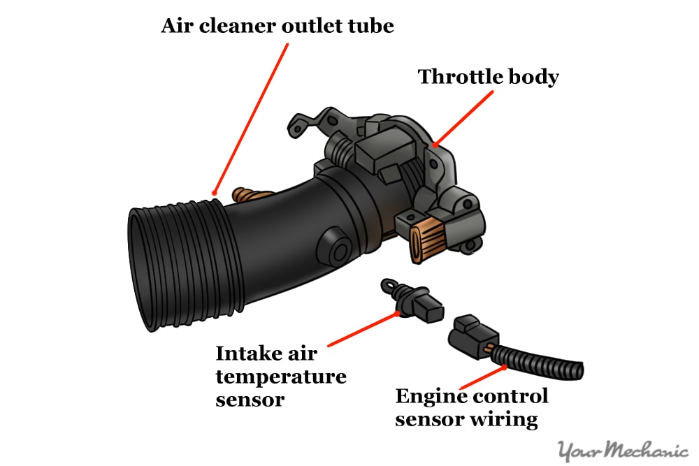
The iat is part of the mass airflow sensor in the air intake.
Gallery of Iat Sensor Wiring Diagram