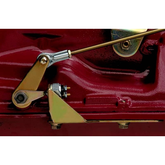
Therefore there is a difference between activating the solenoid by hand and electrically firing it. 1 12 amp holding coil keeps the unit cocked until your engine reaches the selected rpm at which point electrical power is cut to the solenoid and our spring mechanism automatically.

Diagram Based Hurst Shifter Wiring Diagram Completed
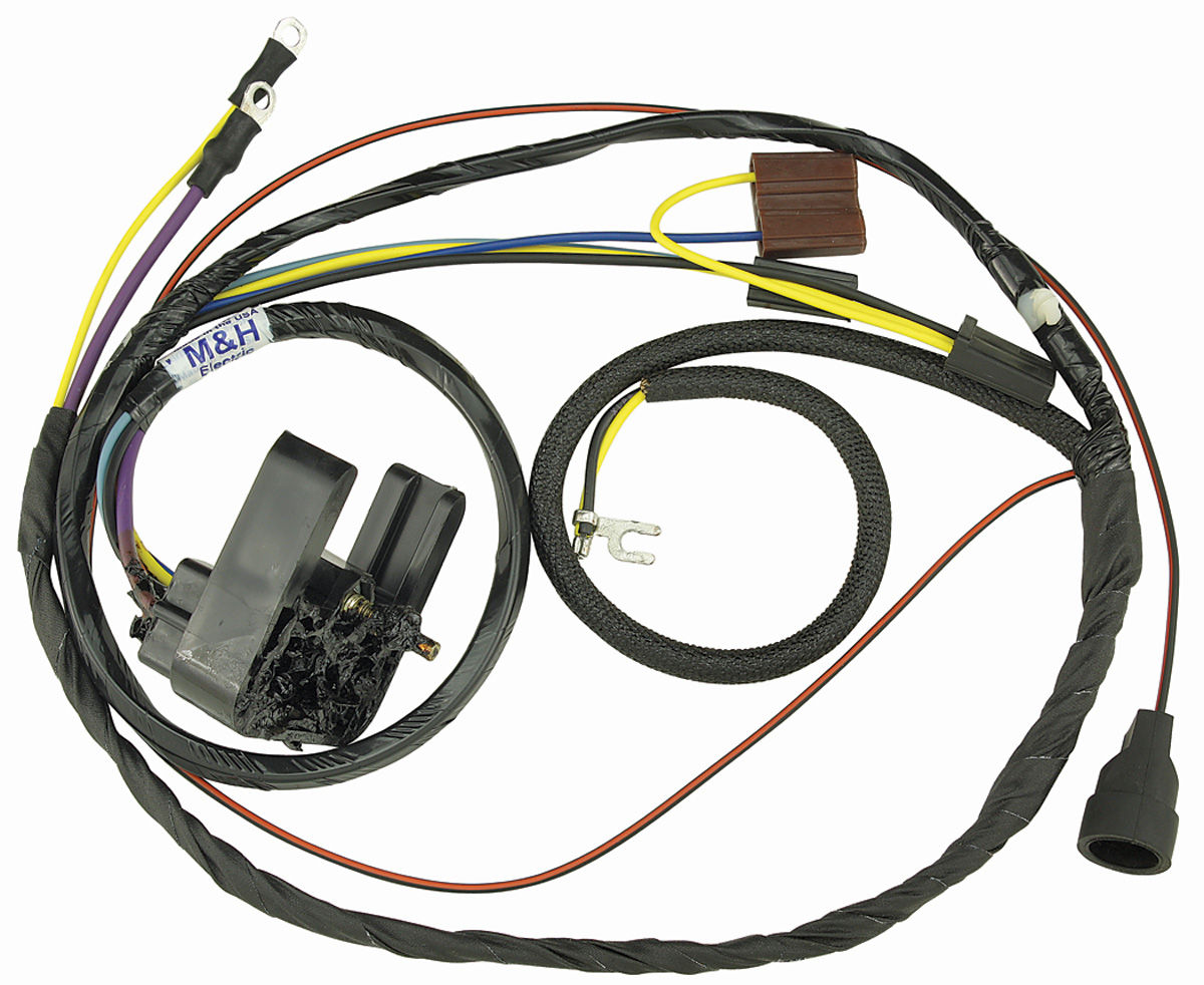
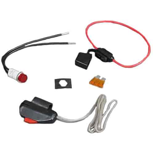
Hurst electric solenoid shifter wiring diagram. If your rpm switch or timer supplies normally open power connect the trigger wire from your device to post 85 on the relay. 13mm socket ratchet extension see wiring diagrams on pages 8 and 9 ground front 13. Hurst uses only quality parts in its electric solenoid shifters such as a hard chromed shaft bronze bushings and a low 3 amp draw coil. Shifnoid or msd use this diagram 87 87 85 85 30 30 86 86 interface relay interface relay shifnoid wiring diagram for a hurst quarter stick or a bm pro stick with a sn5000fc or rc solenoid shift kit 87a 87a not used not used 14 inch gap 14 inch gap 12v to switched side of main battery disconnect switch 12v to switched side of main battery. Shift solenoids instruction manuals part ess electric solenoid shifter universal type part ess 4 pages pdf version updated 71509 electric solenoids push type wiring help electric solenoid tips pdf version updated 82913 be sure to print this out when printing any of the electric solenoids instructions although it is included in the file with the applicable solenoids. You stage and launch the car normally.
Find hurst electric solenoid shifters 2260020 and get free shipping on orders over 99 at summit racing. Attention the attached solenoid is grounded to itʼs mount on the shifter and the shifter is grounded by. With shifter and transmission in neutral check to see that engine starts. Pass wiring through. It does not pull it fully into gear. When testing by.
Connect post 30 to the solenoid. If necessary loosen the screw on the adjusting collar located. Be aware that the solenoid throws the shifter into gear. When the transmission shifter is pulled into low gear the electric solenoid is powered and cocks automatically. Wiring diagram for hurst shifter electric solenoid for a powerglide trans have no instructions cars trucks question. These shifters are designed to be used with most rpm activated switches and come with a universal mounting bracket.
Shifnoid wiring diagram for a hurst quarter stick with a sn5055h three speed solenoid kit. Electric shift kit. Attach 516eyelet connector to black wire of solenoid and ground wire to bolt on strut tower or another appropriate grounding location. Supply post 87 with 12v through a 12 gauge wire. Repeat this with the shifter and transmission in the park position. Using the wiring diagram below as a guideline install the switch wires into your starting circuit.
Dedenbear or digital delay use this diagram shifnoid wiring diagram for a hurst quarter stick bm pro stick tci outlaw or thunder stick shifter with a sn5057 three speed solenoid kit release handle release handle shifter handle shifter handle racthet gate bar racthet gate bar new bolt new bolt r r oid oid to ground to ground to ground.
Gallery of Hurst Electric Solenoid Shifter Wiring Diagram