If you are not sure of how to make the connections on your equipment hire an electrician. Square d latching relay wiring anything wiring diagrams.

Bf 8788 Hand Off Auto Wiring Diagram Wiring Diagram
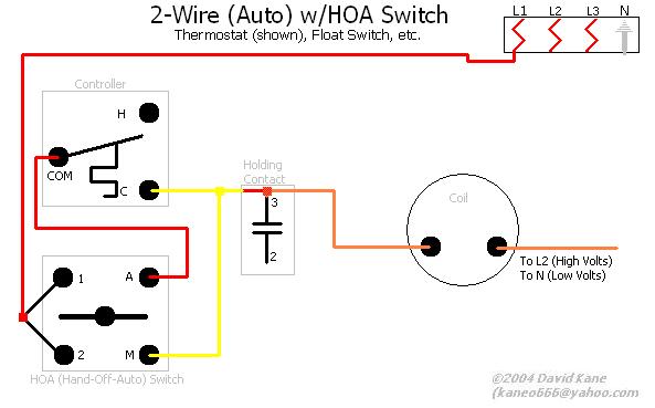
Hoa motor starter wiring diagram. Basic wiring for motor contol circuitry of a starter the two circuits of a motor starter are the power and con trol circuits. We provide sustainable solutions that help our customers effectively manage electrical hydraulic and mechanical power more safely more efficiently and more reliably. Please refer to the manufacturers literature if in doubt. Troubleshooting a two wire magnetic motor starter hand off auto circuit duration. Ladder diagram basics 3 2 wire 3 wire motor control circuit duration. A motor starter is a combination of devices used to start run and stop an ac induction motor based on commands from an operator or a controller.
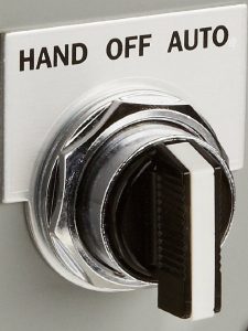
There are two circuits to a starter the power circuit and the control circuit. Ac manual starters and manual motor starting switches 12 class 2510 12 class 2511 and 2512 13 2 speed ac manual starters and iec motor protectors. The switch is shown as a single pole. Hand off automatic controls recognize hand off automatic switches on a schematic diagram. Figure 1 is a typical wiring diagram for a three phase magnetic motor starter. Square d manual motor starter wiring diagram trusted wiring diagrams.
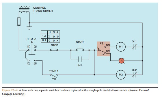
The electricity that passes through the contacts of the starter through the overload relay and out to the motor is called the power. Your motor starter may use wiring which is internal to the starter wiring which is different than the diagrams etc. The circuit shown in figure 271 permits a motor to be operated by a float switch or to be run manually. In north america an induction motor will typically operate at 230v or 460v 3 phase 60 hz and has a control voltage of 115 vac or 24 vdc. Eatons mission is to improve the quality of life and the environment through the use of power management technologies and services. Square d manual motor starter wiring diagram trusted wiring diagrams.
Wiring diagrams do not show the operating mechanism since it is not electrically controlled. They are used in applications which do not require undervoltage protection. Square d motor starter wiring diagram collections of motor starter overload wiring diagram save square d motor starter. Figure 1 typical wiring diagram line diagrams show circuits of the operation of the controller line diagrams also called schematic or elementary diagrams show the circuits which form the basic operation of the controller. Wiring diagrams bulletin 609 manual starters are operated by start stop push buttons mounted on the front of the starter. Hand off automatic controls are used to permit an operator to select between automatic or manual operation of a motor.
Wiring diagram book a1 15 b1 b2 16 18 b3 a2 b1 b3 15 supply voltage 16 18 l m h 2 levels b2 l1 f u 1 460 v f u 2 l2 l3 gnd h1 h3 h2 h4 f u 3 x1a f u 4 f u 5 x2a r power on optional x1 x2115 v.
Gallery of Hoa Motor Starter Wiring Diagram
_2.png)