General descriptions of the operation and maintenance of the ground gard high resistance grounding assembly 3. A grounded system with a purposely inserted resistance that limits ground fault current can flow for an extended period without exacerbating damage.

Application Of Low Voltage High Resistance Grounding In
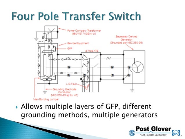
High resistance grounding wiring diagram. What is high resistance circuit detection. High resistance grounding systems high resistance grounding hrg systems limit the fault current when one phase of the system shorts or arcs to ground but at lower levels than low resistance systems. It is quite common to see a low charging alternator due to excessive resistance. This instruction bulletin provides. 61 wiring is to be numbered consistent with the wiring diagrams. Wire numbers are to be on adhesive labels at each end of the wire.
High resistance grounding ieee standard 142 1991 defnes high resistance grounded system as follows. Instructions for installation and placing the grounding assembly into service 4. In the event that a ground fault condition exists the hrg typically limits the current to. High resistance grounding specifications details the minimum technical requirements of high resistance neutral grounding equipment. Ground gard high resistance grounding assembly described in ch 1 general information a. This level of current is commonly thought to be a 10 a or less.
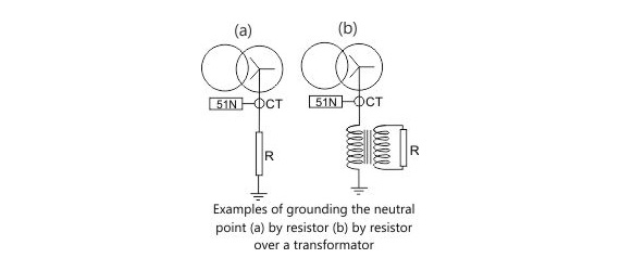
High resistance grounding of the neutral limits the ground fault current to a very low level typically from 1 to10 amps and this is achieved by connecting a current limiting resistor between the neutral of the transformer secondary and the earth ground and is used on low voltage systems of 600 volts or less under 3000 amp. The best way to describe it is by analyzing the alternator charge wire.
Gallery of High Resistance Grounding Wiring Diagram