Ballast wiring diagrams for hid ballast kits including metal halide and high pressure sodium lighting ballasts. If not the arrangement will not work as it ought to be.

Gk 7171 Hid Ballast Wiring Diagram Schematic Wiring
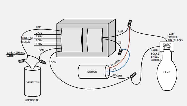
Hid ballast wiring diagram. A ground connection must be made to all ballasts to avoid shock hazard personal injury or damage to the luminaire or installation. A hid ballast hid stands for high intensity discharge is a device that is used to control the voltage and arc current of high intensity discharge lamps during their operation. A ground connection must be made to all ballasts to avoid shock hazard personal injury or damage to the luminaire or installation. Hid wiring diagram hid ballast wiring diagram hid reader wiring diagram hid rp40 wiring diagram every electrical structure is made up of various distinct pieces. Kits available with dedicated taps quad voltage 120 208 240 277 multi 5. Schematics automotive headlamp hid ballast electronic ballast working principle circuit diagram hid ballast schematic wiring diagram database automotive headlamp hid ballast reference design using the an application note stmicroelectronics xentec hid wiring diagram build an efficient hid lamp driver circuit electronic design simple control.
Here we display wiring diagrams for metal halide probe start mercury vapor ballast and high pressure sodium hid ballast kits. Universals hid distributor kits come pre packaged with everything you need for ballast replacement or retrofit. Changing the wiring on a fluorescent light fixture from series to parallel involves changing the ballast from a series to a compatible parallel ballast. Core coil capacitor ignitor if required and mounting hardware all in a ups ready to ship box. Easy access wiring diagram. The circuit diagram for the various types of hid ballasts are shown below.
Hid kitsthe mercury vapor ballast wiring diagram is the blueprint for the ballast circuitry including the input supply voltage and grounding methods. Most magnetic hid ballasts are multi tap meaning they can be connected to several different voltages. Color coated leads for wiring ease. Parallel ballasts can only be wired in parallel according to the diagram on the ballast. A ground connection must be made to all ballasts to avoid shock hazard personal injury or damage to the luminaire or installation. The wiring diagram is the blueprint for the ballast circuitry including the input supply voltage and grounding methods.
Each part should be set and connected with other parts in particular manner. Lifetime warranty and free shipping. 1 lamp rapid start ballast diagram. The wiring diagram is the blueprint for the ballast circuitry including the input supply voltage and grounding methods.
Gallery of Hid Ballast Wiring Diagram