Economizer wiring and is followed by typical control wiring diagrams for single unit applications. No power.

Carrier Great Lakes Pdf Free Download
Hh63aw001 economizer wiring diagram. Before installation review the following before installing the the w7220. 3 power exhaust wiring diagram. Refer to mc4000 leadlag controller instructions manual 2100 563 for dual unit control connections. View profile view forum posts view forum threads. Connect the wires in the harness provided with the terminal block to tb1 on the control board. Power at the n terminal determines the occupiedunoccupied setting.
Apply the wiring diagram to the lower left corner inside of the control box. That economizer control is a honeywell hh63aw001 sent from my samsung sm n920a using tapatalk 01 25 2017 0633 pm 2. 4 secure the damper assembly to the frame using the 1 4 in. W7212 w7213 w7214 economizer logic modules 63 259609 6 table 2. Position the damper assembly so that it will rest on the angle bracket support at the bottom of the economizer frame inside the unit. 2 wiring diagram labels 1 installation instruction package contents table 1 filter sizes economizer pn filter qty and sizes cpecomzr011a00.
If no plug you will have to use wiring diagram and bypass it. Slide the economizer into the unit. The wiring diagrams all terminals ending with a 1 as ground. For further information on mounting and operation refer to honeywell document 63 2700. If the unit is 208230 single phase the 40 va transformer must be replaced with a 75 va. For units with economizer iv controls hh63aw001 w7212 honeywell controller 1.
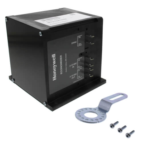
Temperature sensor part 8602 058 c7250a1001 temperature sensor bracket part 113 468 integrated filter supports top view front view wire tie to. Connect the wires according to the diagram provided. Hh63aw001 economizer controller economizer actuator hh57ac080 adjustable dry bulb outside air sensor hh18ha286 low ambient compressor lockout switch economizer plug hood top. If you do it in the control compartment leave a note for the next droid. Operation the purpose of the economizer is to use outdoor air for cooling whenever possible to reduce compressor operation. Jade economizer module model w7220 this document describes wiring power up basic troubleshooting and common installation issues for the jade economizer module model w7220.
Zip economizer energy module wiring diagram econ zip em co2 sensor remote potentiometer 24vac power 2 10vdc signal 24vac power 0 10vdc signal efclsf co2 sensor efc indoor fan low speed relay vfd enable power exhaust fan relay 1 1 power source should be same as econ zip base purge contact thermostat. Page 46 section 3 types of analog economizers when wiring any economizer it is very a rule of thumb to follow any honeywell important that you read the notes on the electronic economizer logic module will have correct wiring diagram. Uncrate the economizer assembly. Ua local 32 retired as of jan. 24 vac occupied. With main power shut off mark minimum position.
Bundle the power exhaust wiring harness to existing control box wiring harness with 6 of the supplied.
Gallery of Hh63aw001 Economizer Wiring Diagram