Wiring diagrams and electrical schematics are provided in. Generac generator wiring diagram collections of briggs and stratton power products 1006 1 megaforce 6500 parts.

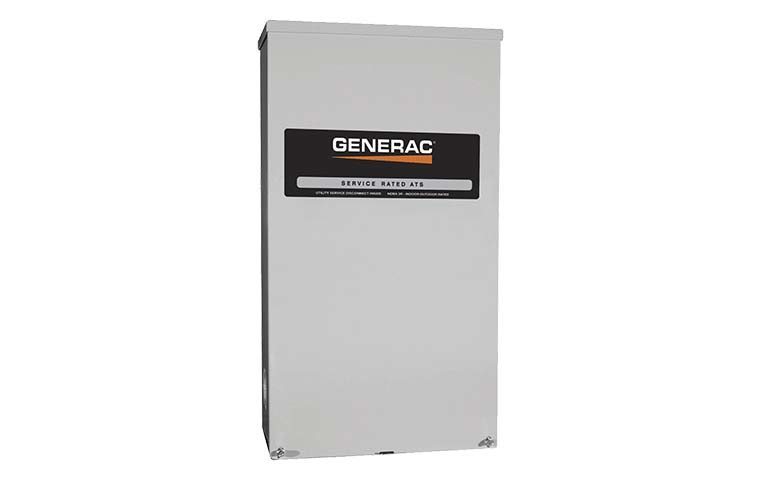
Generac Rxsw200a3 200 Amp Service Rated Automatic Transfer
Generac load shed wiring diagram. 4390 generac generator wiring schematic simple electronic. Generac ats wiring diagram download. To prevent possi ble injury if such a start and transfer occur always set the generator to the off mode remove the 75a fuse. Generac gts w type transfer switch installing the switch includes the following proce dures. Use at least 75 ºc rated wire and gauge per installa. When an automatic transfer switch is installed for a standby.
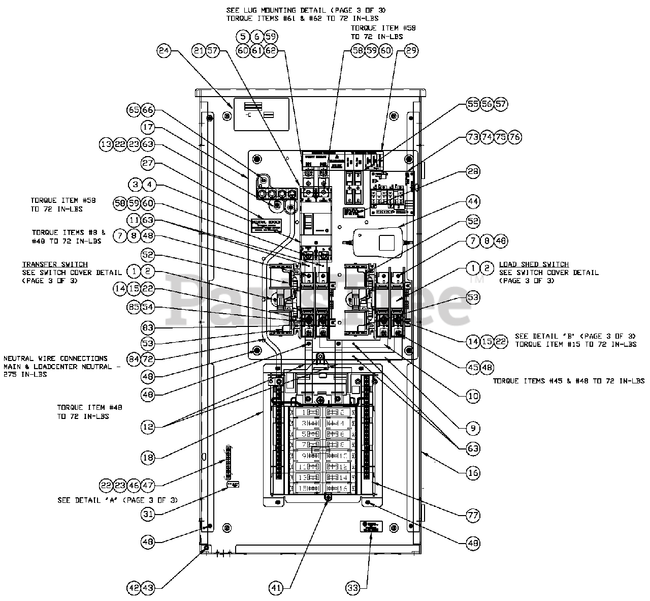
Parts manual ev unit ev assembly 200a se csa. And get immediate medical help. Installation diagram csa 100a. Vernonia living 13961 views. Generac 16kw guardian with load shed duration. Input from generac load shedding can be connected to outputs 1 4 jumper.
Turn off both utility normal and emergency standby power supplies before connecting power source and load lines to transfer switch and smm. Generac generator transfer switch wiring diagram image. Enter your model or serial number to find generac specifications manuals parts lists faqs how to videos and more for your product. Accessories click to buy accessories. Parts manual ev unit ev assembly 100a se csa. Generac 16kw whole house power backup duration.
Wdsd serv ent xfer sw. Wd load shed transfer switch. 12 volts dc only 12 volts dc 5 4 3 2 1 12 volts dc tb no nc c 1 r y psp products inc. Suitable conduit fittings must be installed in knockout openings when running supply and load wires. Installation diagram csa 200a 0h5574. Benjamin sahlstrom 204042 views.
When this occurs load circuits are transferred to the standby generator power source. Position for generac load shedding modules load shedding relay module generac wiring diagram caution. Load shedding relay module wiring diagram 1 to 4 magnetic latching relays configured for direct connection to kohler load shedding module wiring configuration for 120 volt ac input normally closed contactor emulator wiring diagram shown for 1 4 magnetic relay models.
Gallery of Generac Load Shed Wiring Diagram