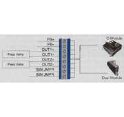
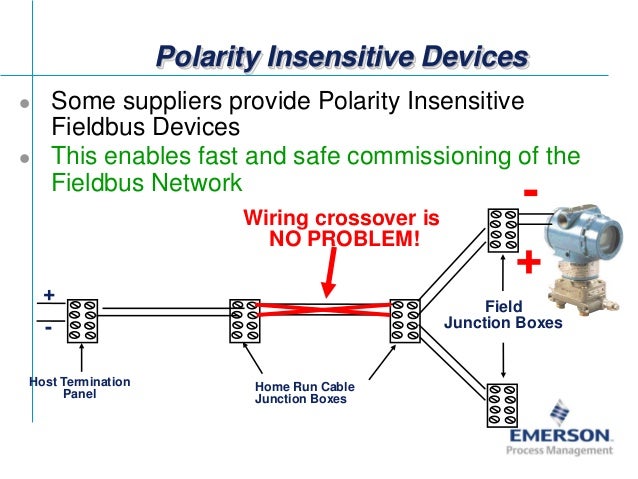
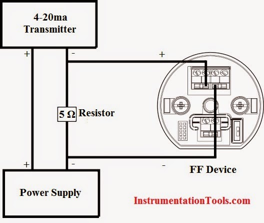
Twisted pair to carry digital signals. Is illustrated in figure figure shows the fourconnect to an externally powered foundation fieldbus device for small fieldbus segments the power conditioner and terminators can be contained in a single wiring block.

Foundation Fieldbus Paktechpoint
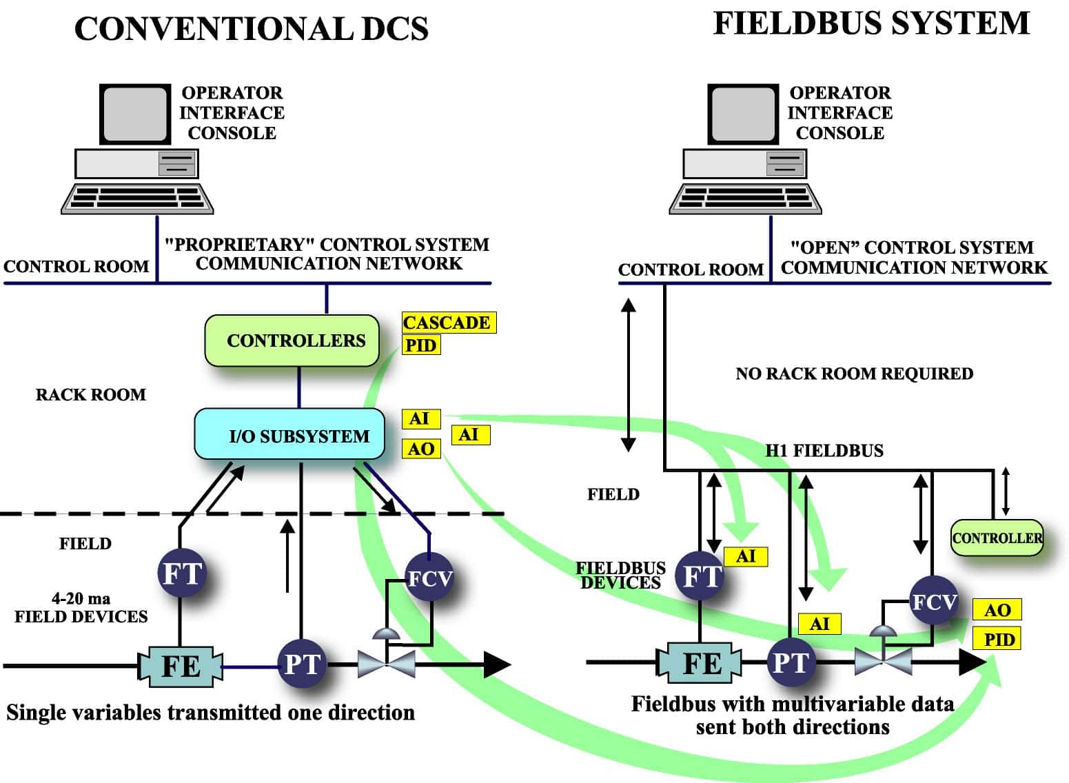
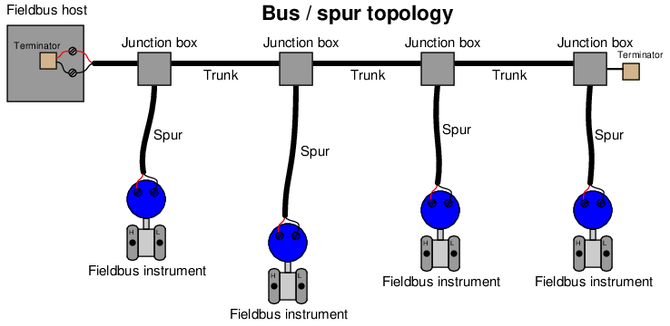
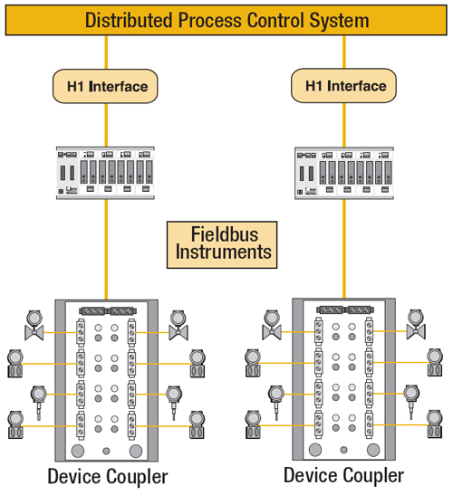
Foundation fieldbus wiring diagram. The devices use the shared wiring system to get their power and to send signals to one another. The trex unit draws 0 ma when it is offline. For wiring and installing a foundation fieldbus network. A fieldbus segment is made up of one or more segments. Fieldbus wiring guide th fourth edition of relcoms fieldbus wiring guide covers a wide array of fieldbus physical layer topics. Such a network is defined as a digital two way multi drop communication link among multiple intelligent field devices and automation systems as defined by the fieldbus foundation specifications.
A power conditionerc is needed to separate a conventional power supply from the fieldbus wiring. Jonas burge isbn 1 55617 760 7 foundation fieldbus. Ian verhappen and augusto pereira. Foundation fieldbus wiring basics. Fieldbus is defined in isa standard 5002 section 24. This topologyfrom the diagrams in this section.
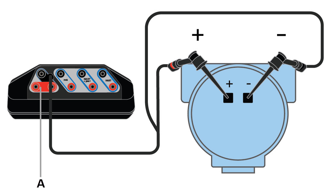
The trex unit draws approximately 12 ma from the fieldbus segment when it is online. The fieldbus cable provides power to the attached devices. Click the image or button to download it. There is more to fieldbus than the wiring. Fieldbuses for process control. Remove the usb cable from the trex unit before connecting to a device.
Wiring diagrams for foundation fieldbus devices and the field communicator application. For those wanting information about how fieldbus works to control a process refer to. Fieldbus foundation 9005 mountain ridge drive bowie bldg.
Gallery of Foundation Fieldbus Wiring Diagram


.jpg)