I have seen very few pickup coils on ford tfi systems go bad. It was used on a number of fords engines the efi 50 engines in particular.
Does Anyone Know Where This Wire Goes Mustang Forums At
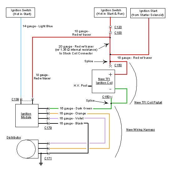
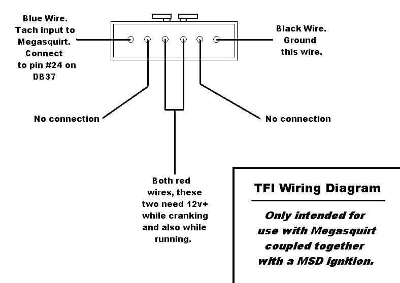
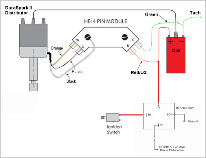
Ford tfi distributor wiring diagram. Tfi ignition control with megasquirt ii. You can find the ignition control module test explained here. Testing the pickup coil pip in the distributor is not an easy task and best to test the tfi module first then replace the pickup coil pip if the tfi module tests ok. Ive been casually looking at the wiring diagram of the sn95 distributor on and off for months trying to figure out if there is a way to incorporate this distributor into a tfi relocation project ive been eyeing for my 93 gt. See the trouble shooting basic procedures article in the general trouble shooting section. Check the diagrams in your instruction manual itll have a picture of what goes where when using a tfi distributor.
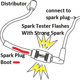
The tfi module is a gray box fitted to the side of the distributor. Today i looked at it and had what i think was an epiphany. Test the tfi module according to the chart below. The above surface is unacceptable. The tfi module surface looks like this. The tfi module is a gray box fitted to the side of the distributor.
Thick film ignition tfi modules were used on ford vehicles with distributors from the early 1980s to the mid 1990s. Courtesy of ford motor co. A very first look at a circuit representation could be complicated yet if you could check out a subway map you can read schematics. You can find the 1994 1995 ignition system wiring diagram here. How to test the ford ignition control module. Ford tfi wiring diagram a beginner s overview of circuit diagrams.
It shows the elements of the circuit as simplified forms and the power and signal links in between the devices. See wiring diagram for wire color id. It is about one inch wide and about four inches long. The conventional ford distributor with tfi module depends heavily on engine fan airflow for cooling. Ford ignition system circuit diagram 1994 1995 49l 50l and 58l. 6al doesnt do that most of the digital series boxes do.
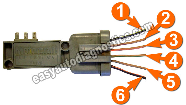
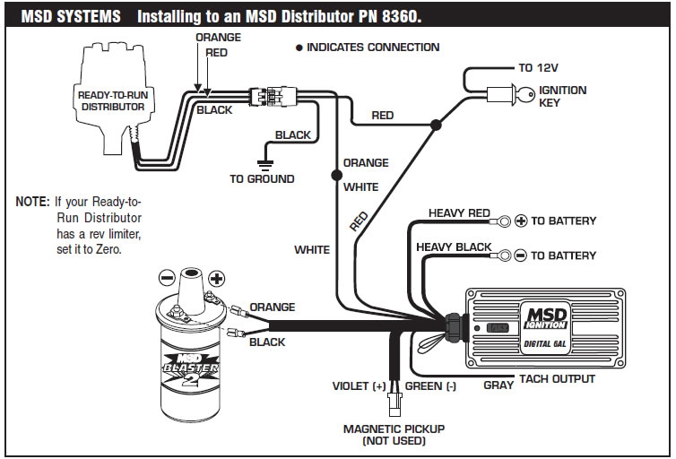
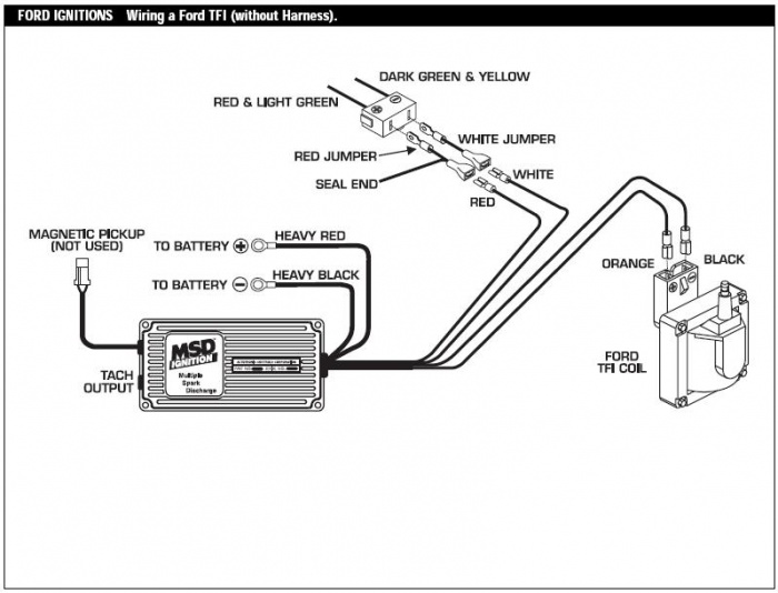
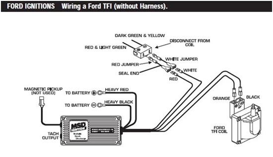
Thick film ignition tfi modules were used on ford vehicles with distributors from the early 1980s to the mid 1990s. In the next page youll find the icm connectors pinout with a brief description of each wire. Altering airflow in any way that reduces air across the engine front and across the distributor will increase tfi module temperature. It was used on a number of fords engines the efi 50 engines in particular. Have to use the white wire input or you can ditch the tfi module and wire the pickup direct but you must have a msd box with the option of a hall effect sensor input. Tfi iv ignition system wiring diagram courtesy of ford motor co.
A wiring diagram is a streamlined standard photographic depiction of an electric circuit. Variety of ford tfi wiring diagram.
Gallery of Ford Tfi Distributor Wiring Diagram