Flashers and hazards turn signal flasher wiring diagram wiring diagram contains numerous comprehensive illustrations that display the link of varied products. A wiring diagram is a simplified conventional photographic depiction of an electric circuit.
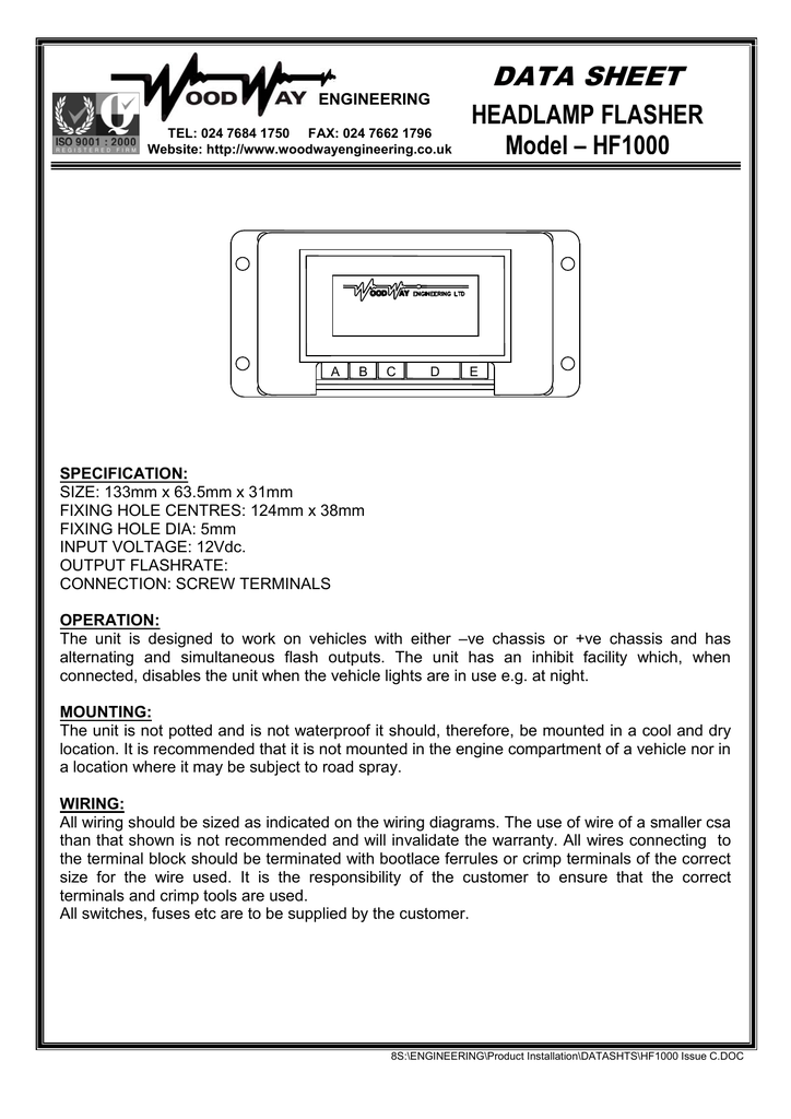
Hf1000 Woodway Engineering
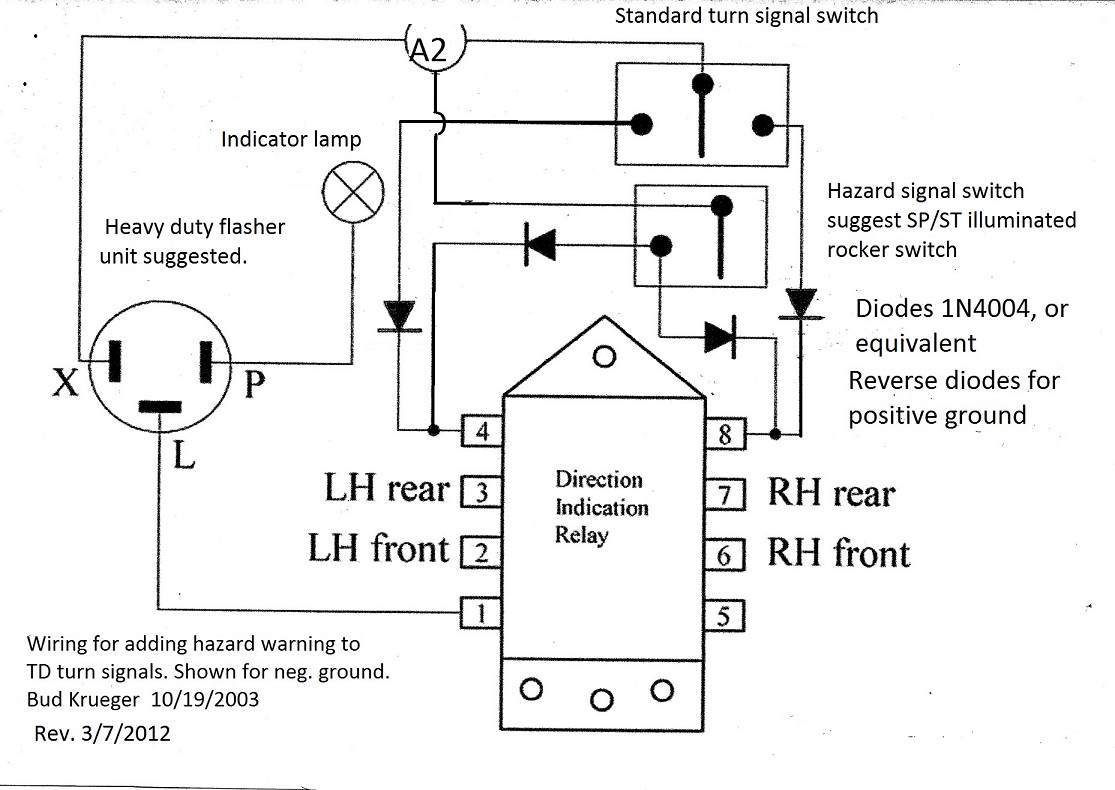
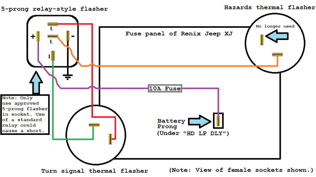
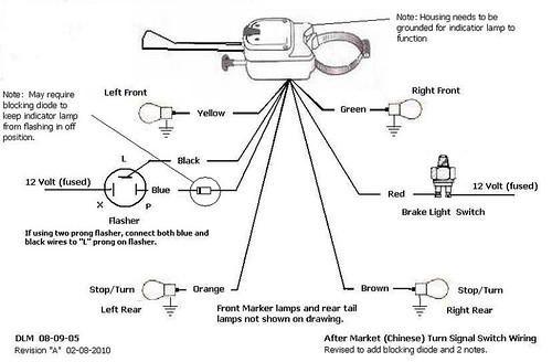
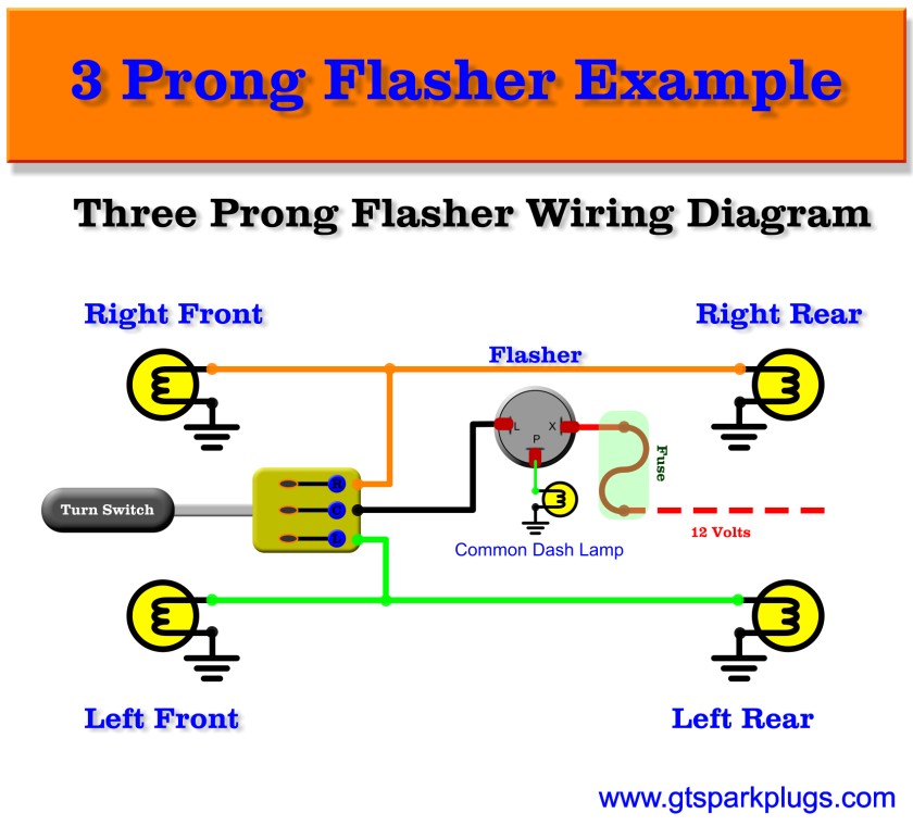
Flasher wiring diagram. A wiring diagram generally provides details regarding the relative placement and also plan of gadgets and terminals on the tools in order to help in building or servicing the gadget. 3 prong flasher wiring diagram 3 pin flasher relay wiring diagram 3 pin flasher wiring diagram 3 prong electronic flasher wiring diagram every electric arrangement is composed of various unique components. From there it goes to the stalk on the steering column. Standard scooter flasher units have two major drawbacks. Audio circuit diagrams lcd led display no comments. Simple 12v horn wiring diagram readingrat net within flasher relay jpg resize u003d665 2c580 with 2 pin wiring diagram relay diagrams tearing in 2 pin flasher we collect a lot of pictures about 2 pin flasher relay wiring diagram and finally we upload it on our website.
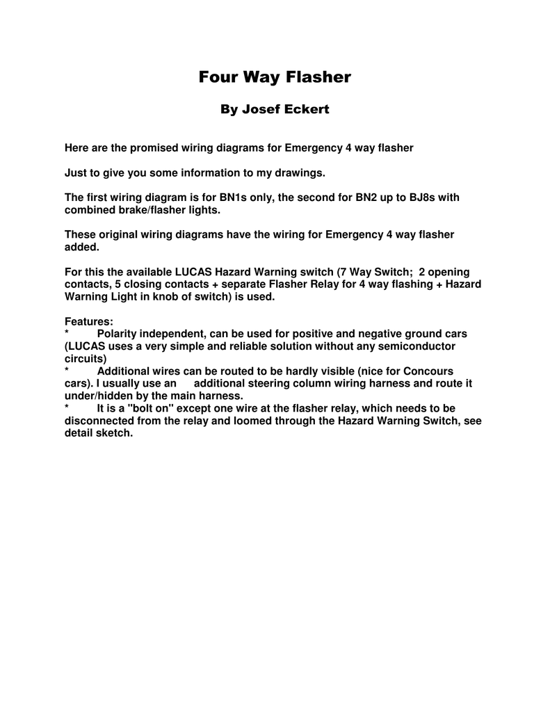
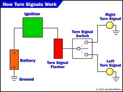
The power goes through a fuse panel into the thermal flasher. Collection of 3 pin led flasher relay wiring diagram. Many good image inspirations on our internet are the best image selection. It includes instructions and diagrams for various kinds of wiring strategies and other things like lights home windows and so on. Lets take a look at how the turn signal circuit is hooked up. Each part should be placed and linked to other parts in specific way.
Each component should be placed and connected with different parts in specific way. Each part should be set and connected with different parts in specific manner. It shows the components of the circuit as streamlined forms and the power and signal links between the devices. Turn signal flasher wiring diagram led turn signal flasher wiring diagram motorcycle turn signal flasher wiring diagram turn signal flasher circuit diagram every electric arrangement consists of various unique parts. If not the structure wont work as it ought to be. It reveals the elements of the circuit as streamlined forms and the power and also signal links between the devices.
2 pin flasher relay wiring diagram 2 pin flasher relay circuit diagram 2 pin flasher relay wiring diagram 2 pin indicator relay wiring diagram every electrical structure consists of various diverse parts. A wiring diagram is a streamlined standard pictorial representation of an electrical circuit. Otherwise the arrangement wont function as it should be. First of all they need a high enough operating current to make them switch. If not the structure will not work as it should be. December 24 2018 in.
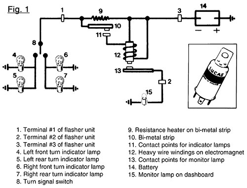
It shows the components of the circuit as simplified shapes and the knack and signal contacts in the company of the devices. Assortment of led flasher wiring diagram. Galls wig wag flasher wiring diagram wiring diagram is a simplified within acceptable limits pictorial representation of an electrical circuit. Universal 3 wire flasher unit schematic circuit diagram. Universal 3 wire flasher unit schematic circuit diagram. The turn signal circuit gets power when the ignition key is on.
Gallery of Flasher Wiring Diagram