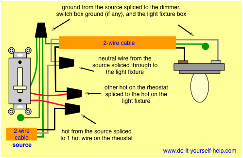
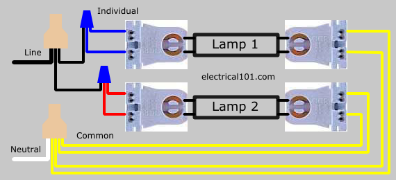
The source is at sw1 and 2 wire cable runs from there to the fixtures. The hot and neutral terminals on each fixture are spliced with a pigtail to the circuit wires which then continue on to the next light.

Fixture Adapter Wiring Diagrams Avi On Labs Support
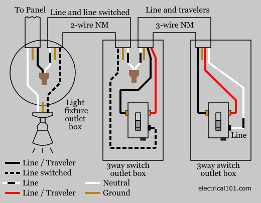
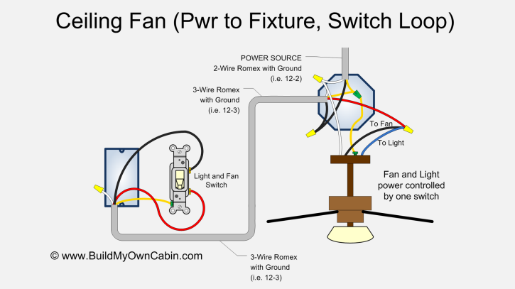
Fixture wiring diagram. Electrical circuit electric circuit listing the size of the home electrical service panel is designed by calculating the square footage of the home and factoring in the code requirements for the electrical circuits that are required. New 2 wire cable is run from the receptacle to the new light fixture. Two lengths of four wire with ground cable joined at the fixture box link the right and left switch traveler terminals to each other and to the fixture. These are commonly used to turn a table or floor lamp on and off from a wall switch. This diagram illustrates wiring for one switch to control 2 or more lights. In this diagram power enters the fixture box.
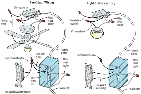
Wiring a light switch diagram 1. Each part ought to be set and linked to different parts in specific way. The wiring in this diagram is for adding a new light fixture to a switched outlet ie. The black wire of the fixture is for the power connection which typically connects to the black wire of the electrical box. For more information about circuit wiring circuit wiring electrical. Light fixture wiring connections.
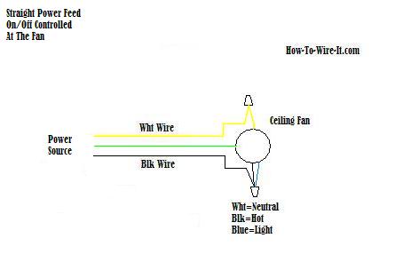
Light fixture wiring diagram bathroom light fixture wiring diagram ceiling light fixture wiring diagram emergency light fixture wiring diagram every electric structure is composed of various unique components. One that is hot only when a switch is on. The incoming hot wire is connected to the right switchs common terminal. The following connections are typical for 120 volt light fixtures and wiring diagrams may be reviewed for further understanding. If not the structure wont work as it should be.
Gallery of Fixture Wiring Diagram