Alarm system wiring from the transformer location to the main panel should be 4 conductor fire wire 22 gauge minimum. Devices and a fire alarm control panel facp with remote noti in rooms used by the system for the connection of alarm transmission wiring communications and other training exercises to.

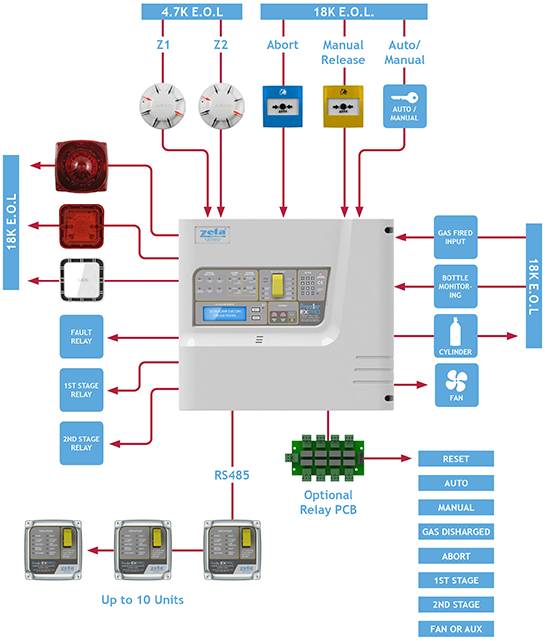
Conventional 2 Zones Fire Alarm Control Panel
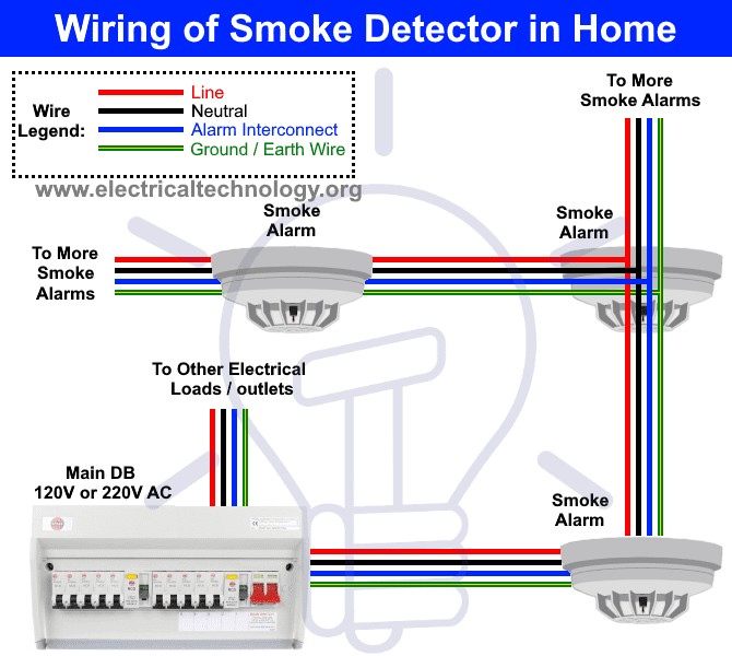
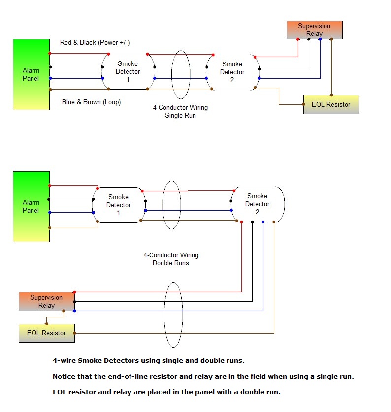
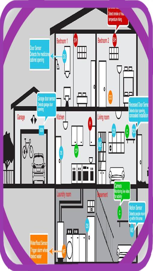
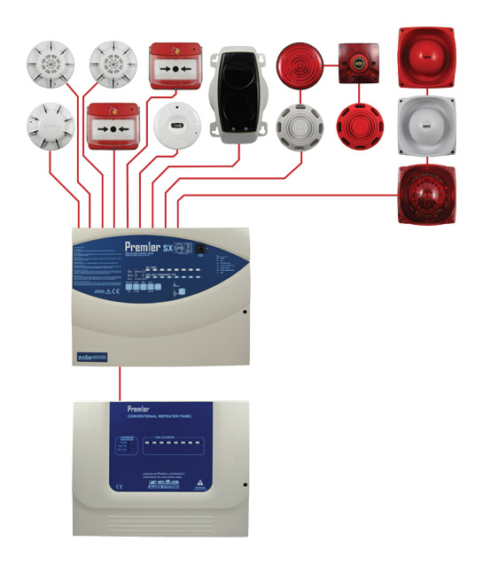
Fire alarm system wiring diagram. Fire alarm training system training documentation for the training of hisher staff at the purchasers detection circuit using input module class b. Types of fire alarm signals and differences between conventional addressable and analogaddressable fire alarm systems are also presented. The common elements inside a wiring diagram are ground power wire and connection output devices switches resistors logic gate lights etc. In our basic wiring diagram a single or multiple heat and smoke detectors are installed in the home by connecting the live line or hot neutral ground and an interconnected wire to the alarm. It reveals the components of the circuit as streamlined forms and the power as well as signal links in between the devices. Main lines are represented by l1 l2 and the like.
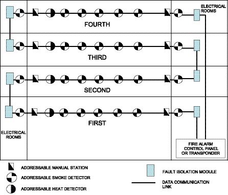
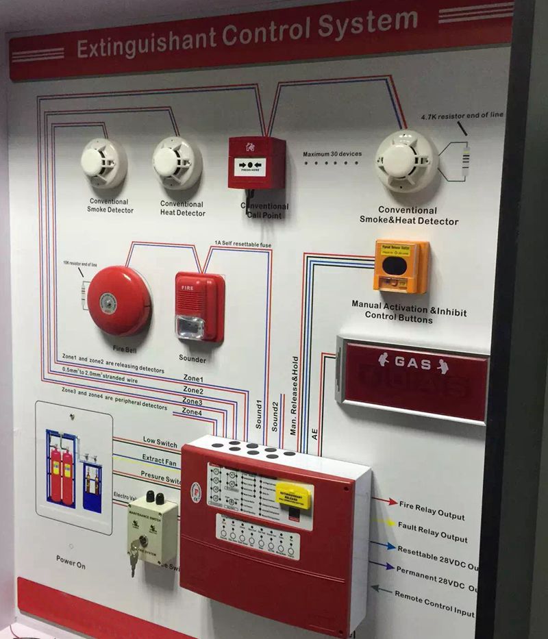
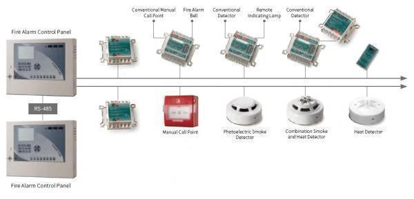
Assortment of fire alarm system wiring diagram. The information shown for each control panel includes wiring diagrams and circuit tables. During fire if a wire breaks class a wiring provides an alternate route for signals to pass between field devices and the fire alarm panel. A wiring diagram is a simplified standard photographic depiction of an electrical circuit. Class a wiring in a fire alarm system uses a primary signal path to all the devices and if the signal path is interrupted class a wiring uses the class a return wires as an alternate pathway the signals. Wellborn variety of addressable fire alarm system wiring diagram.
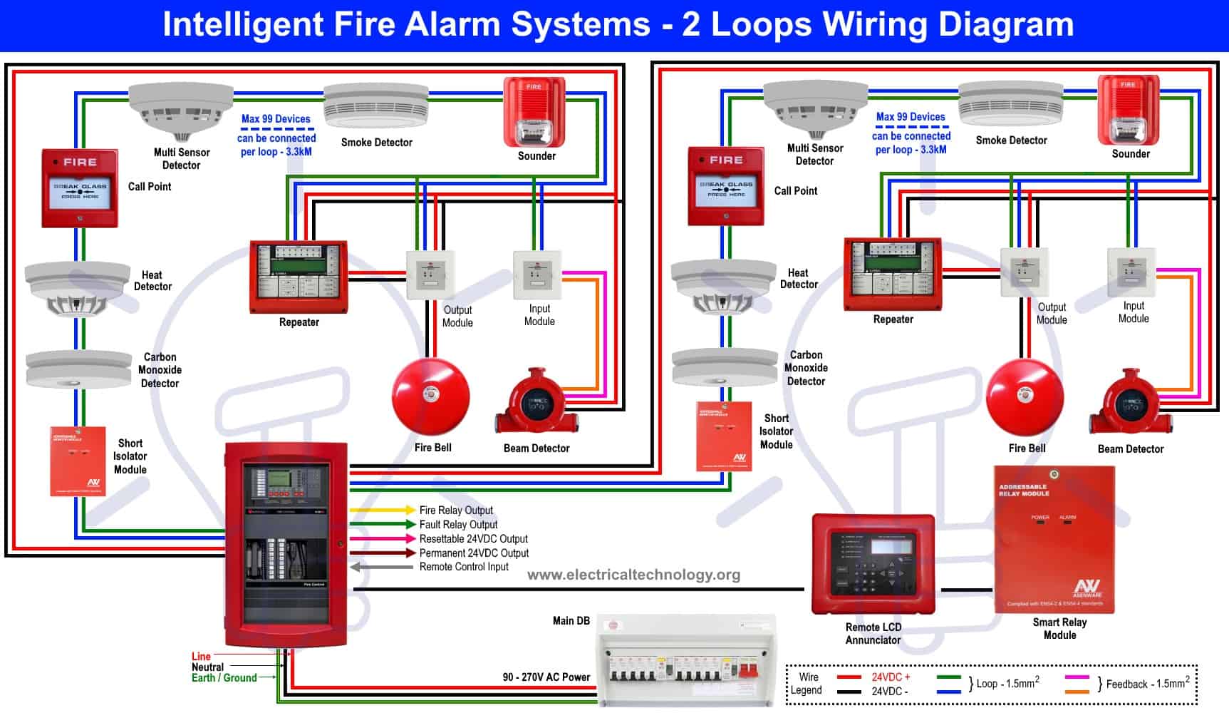
Addressable fire alarm system wiring diagram. Collection of fire alarm wiring diagram pdf. It reveals the elements of the circuit as simplified forms and the power and signal connections between the devices. November 7 2018 by larry a. Requirements for est products and systems fire alarm security access control cctv published by edwards systems technology in conjunction with paige electric co lp. Run the wire to an unswitched electrical outlet as close to the panel as possible.
It reveals the elements of the circuit as simplified shapes as well as the power and signal connections between the gadgets. System wiring explains the differences between slc class a and class b circuit wiring use of isolators to provide greater system reliability and other wiring options ie initiating. This is the basic fire alarm system used in household wiring. A wiring diagram is a streamlined traditional photographic depiction of an electric circuit. The circuit type is designated with a letter a z. A smoke or heat detector can be installed to the existing or new home wiring.
A wiring diagram is a simplified standard photographic depiction of an electric circuit.
Gallery of Fire Alarm System Wiring Diagram