Is recommended 24 vdc circuit 3 4. It shows the components of the circuit as simplified shapes and the capacity and signal associates together with the devices.

Dk 9767 Wiring Diagram Together With Security Alarm Circuit
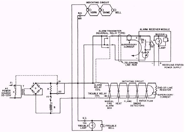
Fire alarm control module wiring diagram. To next control module or end of line relay. Fire alarm control module wiring diagram wiring diagram is a simplified customary pictorial representation of an electrical circuit. Box and the control module must be placed into the barrier and at tached to the junction box figure 2a. Siga rel 69 isolator module. The power limited wiring must be placed into the isolated quadrant of the module barrier figure 2b. Fire alarm security access control cctv published by edwards systems technology in conjunction with paige electric co lp.
An esz is a discrete area of a building bounded by smoke or fire barriers in which occupants are intended to relocate or evacuate. Break wire run to provide supervision. Install module wiring in accordance with the job drawings and appropriate wiring diagrams figures 3 10. An automatic fire alarm systemtypically made up of smoke detectors heat detectors manual pull stations audible warning. Refer to notifier manual. 5 for frm 1 general fcm 1 control module the fcm 1 addressable control module provides notifier intelligent control pan els a circuit for notification appliances horns strobes speak ers etc or to monitor a telephone circuit.
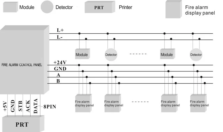
Some control panels have relay built in and do not require external wiring. Level 0 means no survivability is required wiring within the esz level 1 3 indicate that attack by fire shall not impair the control and operation of notification appliances outside the esz. Siga im 70 audio. One relay required for each circuit. Module polarities are shown in alarm connect modules to listed compatible 32 vdc max. Fire alarm system is the combination of different components such as smoke detector heat detector carbon monoxide detector multi sensor detector call points sounders bells relay module repeater annunciator fire control panel and other related and optional security devices designed for fire alarm control system.
The circuit type is designated with a letter a z. Addressability al lows the fcm to be activated either manually or through. Fcm 1 module see wiring diagram fig. 2 firelite slc wiring manual pn 51309r2 3192019 fire alarm emergency communication system limitations while a life safety system may lower insurance rates it is not a substitute for life and property insurance. The information shown for each control panel includes wiring diagrams and circuit tables.
Gallery of Fire Alarm Control Module Wiring Diagram