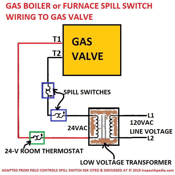
Block the vent pipe with a noncombustible material. Search the field controls wring diagram library for all wiring disgrams on field controls products.
Power Inverter Installation Magnum Dimensions
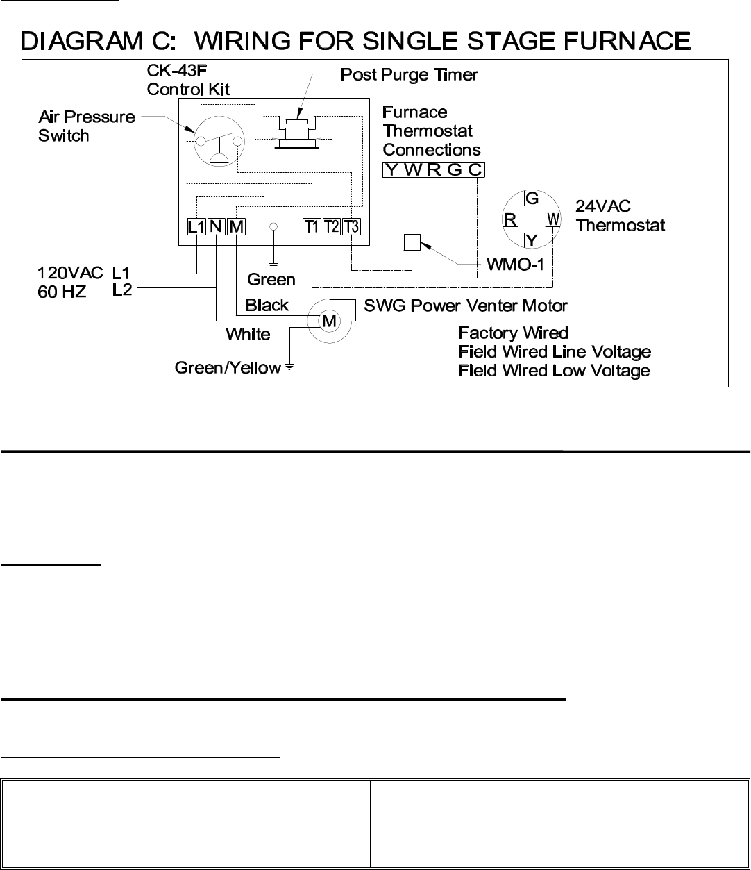
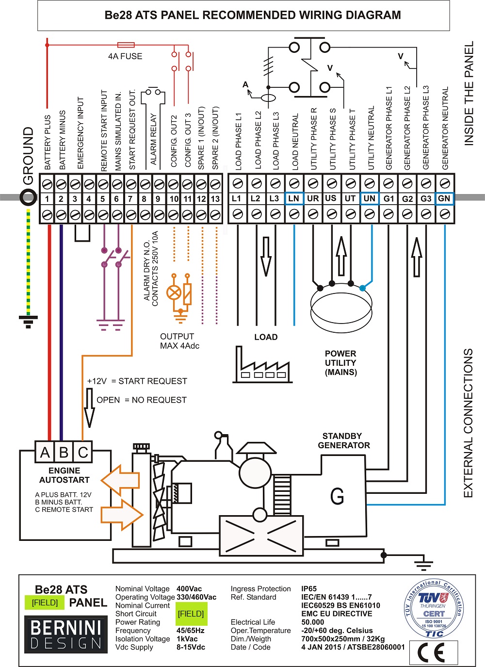
Field power venter wiring diagram. Combo vent is the safest most efficient power venter available today the combovent cv combines the motor blower and vent hood in one complete easy to install unit. Mount the power venter through the wall keeping the outer pipe centered in the hole. Wiring instructions wire the venter motor and controls in accordance with the national electrical code manufacturers recommendations andor applicable local codes. Single wall vent pipe refer to diagram b may be used to join the appliance to the power venter. The wiring should be protected by an over current circuit device rated at 15 amperes. If wmo 1 switch is installed allow vent system to cool.
After determining the location of the venting system termination point see diagram a cut a square hole through the wall 1 larger than the outer pipe diameter of the power venter. Field controls ck 63 venterburner control system for oil systems control kits ck control the operation of swgcv power venters. Check ground circuit to make certain that the unit has been properly grounded. This should open the pressure switch contacts and stop burner operation. Cas 4mv ck 81 chimney vent single 750mv gas appliance wiring diagram. Swg replacement motor kit instruction manual.
1 swgii 4hd sidewall power venter. Fields power venter wiring diagram field controls 46457800 user manual fields power venter wiring diagram wiring diagram is a simplified welcome pictorial representation of an electrical circuit. May require optional delay oil valve for simultaneous burner operation. A power venter uses a motorized blower to vent the products of combustion. This equipment is designed to. Wiring diagram for model cas 4mv power vent single 750mv gas appliance combustion air system.
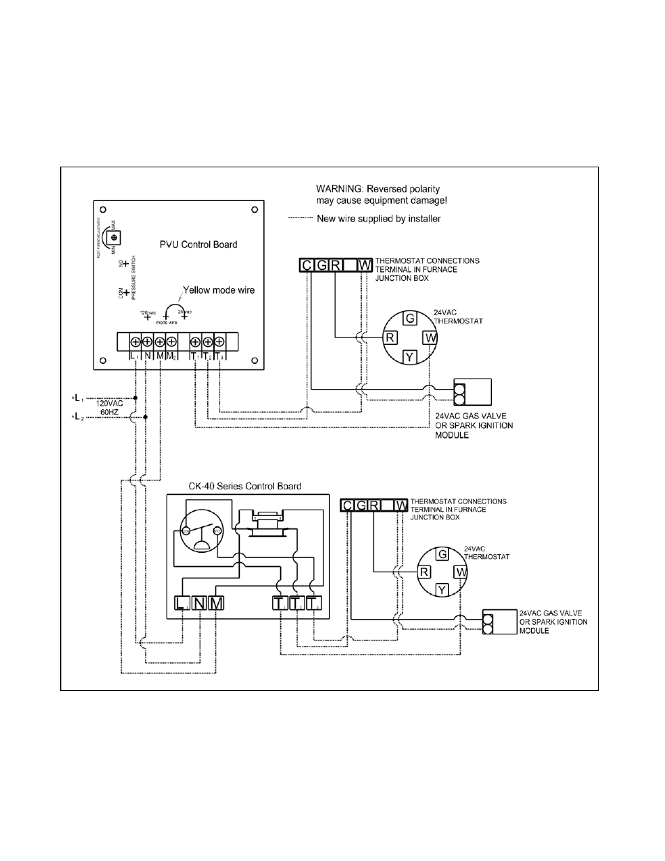
Power venting or sidewall vent is more economical and safer than a chimney vent. Connecting power venter to appliance figure 3 figure 4 diagram a 3. A power venter is interlocked with the appliance to ensure that proper draft is achieved before the appliance burner is activated. While system is operating disconnect power to the venter motor. Installation manual and wiring diagrams for models swg ii 5 swg ii 6 aga and swg 8 sidewall power venter kits. Sidewall power venting kit model.
See the chart below to select the proper kit for your application. Swg 4g items included in kit. Control kits can also control the operation of field draft inducers. Disconnect power supply before making wiring connections to prevent electrical shock and equipment damage. Search by combustion air treatment or ventilation. Disconnect the vent pipe between the venter inlet and the appliance outlet.
It shows the components of the circuit as simplified shapes and the gift and signal associates along with the devices. The combovent mounts on the outside of the building and pulls the combustion gases from the appliance through the outside wall utilizing 100 negative pressure.
Gallery of Field Power Venter Wiring Diagram