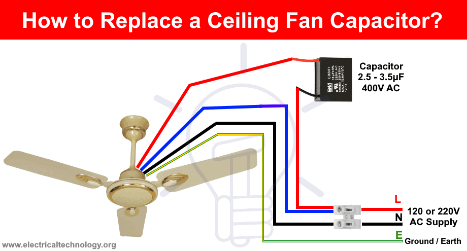
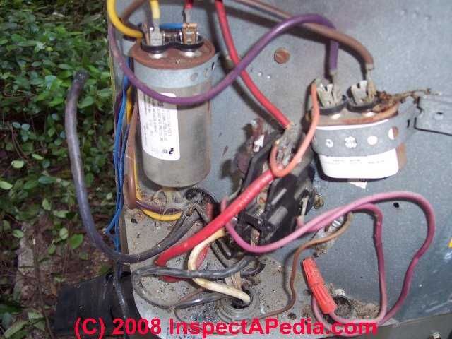
Double check your connections using the fan wiring diagrams. Checking the motor and capacitor connections.
Why Is A Capacitor Used In A Fan Quora
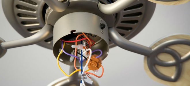
Exhaust fan wiring diagram with capacitor. I took it apart. Can someone please help me out. The bathroom exhaust fan stopped spinning all of a sudden. Each component ought to be placed and linked to different parts in particular manner. Level flight at clxxx this appears only on the in flight analysis and only if the wing area and airframe weight were specified. I got a new capacitor however i seem to have forgotten how this thing was wired.
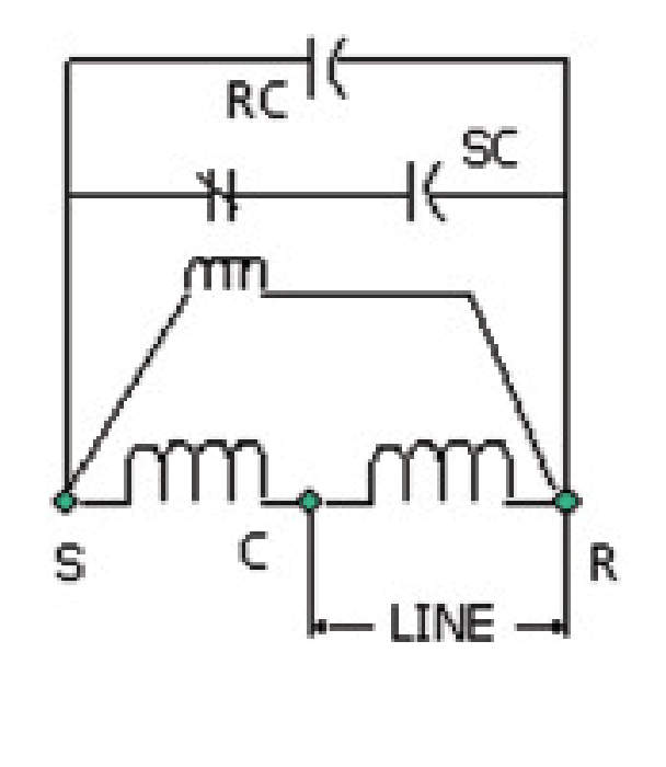
The motor seems ok to me its not burnt or anything. 8w 30 automobile electronics pdf manual download. Below is the circuit diagram of split phase induction motor in a ceiling fan clearly showing a capacitor connected in series with the starting winding auxiliary winding. Here you can use the same exhaust fan and change the electrical wiring to the circuit relay and then it becomes automatic exhaust fan. Electric motor capacitor wiring diagram exhaust fan wiring diagram with capacitor new new wiring diagram for electric motor with capacitor. Exhaust fan wiring diagram with capacitor.
Log in or register for your pricing. Table fan motor repair exhaust fan motor repair खड खड क आवज आन 5 मनट म सह कर 10 रपए म duration. Smoke exhaust fans are need to run when presence of smoke but most exhaust fan runs without any use and increases electricity utilization to avoid this situation automatic smoke exhaust fan circuit developed with easily available components. Easy ordering convenient delivery. Before go in details about why a capacitor is connected in series with the auxiliary winding let is know what will happen if there is no capacitor in a ceiling fan. I think the capacitor is probably shot.
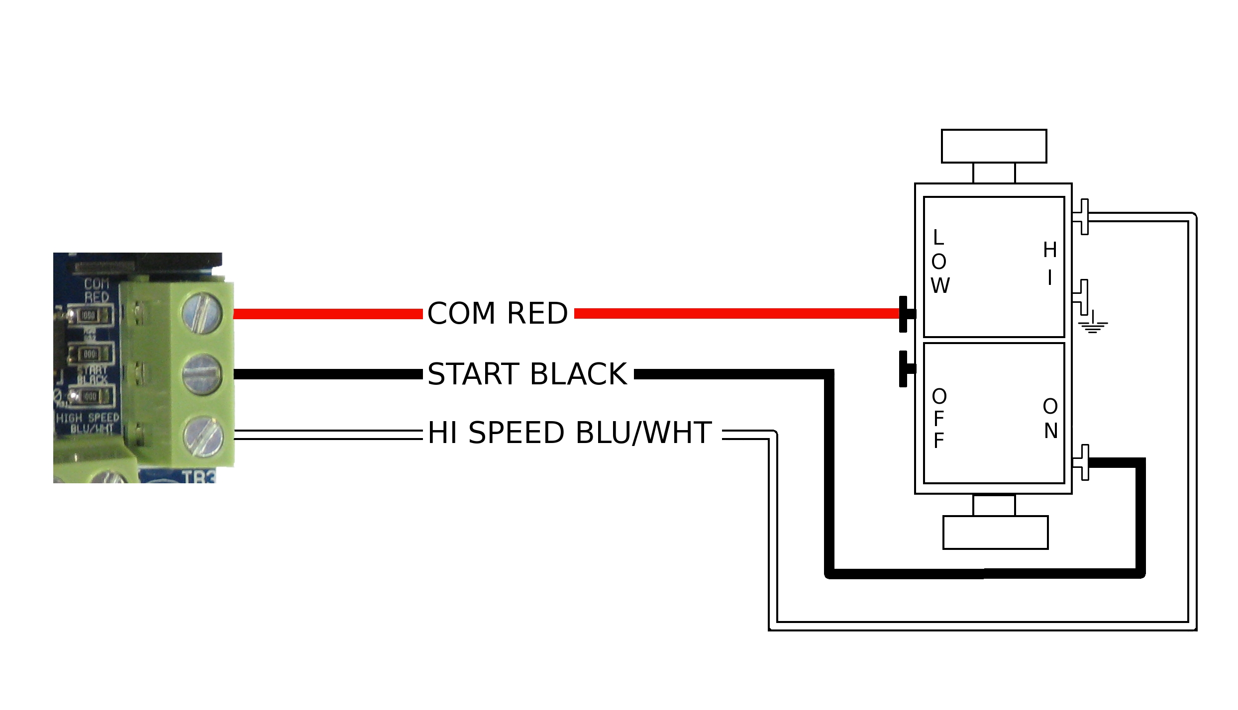
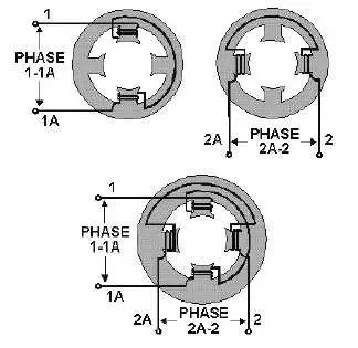
The concern is that there is a capacitor for the motor. How to verify fan motor wiring connections. So im thinking that the motor may have to start with the slower. 3ø wiring diagrams 1ø wiring diagrams diagram er9 m 3 1 5 9 3 7 11 low speed high speed u1 v1 w1 w2 u2 v2 tk tk thermal overloads two speed stardelta motor switch m 3 0 10v 20v 415v ac 4 20ma outp uts diagram ic2 m 1 240v ac 0 10v outp ut diagram ic3 m 1 0 10v 4 20ma 240v ac outp uts these diagrams are current at the time of publication. Single phase motor wiring diagram with capacitor baldor single phase motor wiring diagram with capacitor single phase fan motor wiring diagram with capacitor single phase motor connection diagram with capacitor every electrical arrangement is made up of various unique pieces. You should see that there is a separate motor winding for high speed.
Graingers got your back.
Gallery of Exhaust Fan Wiring Diagram With Capacitor