Module with a known good module either from stock or from a vehi cle that is currently running. Using the rear brake to stop.

Eton Viper 50 Wiring Diagram Viper Wiring Diagram 70 Wiring
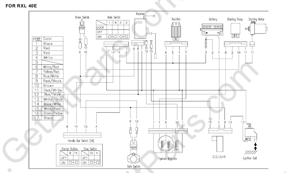
Eton viper 50 wiring diagram. Then waiting ten seconds later pull out end of wire clip from receiver pin or frame ground. Eton america llc viper 50 50m 70 90 90r loss of spark check list scl 0002 6212004 page 3 of 3 fourth step is to replace the cdi. Before testing the remote controller make sure the engine stop switch on the left handle bar is on position. View and download e ton viper 50 st service manual online. The rear brake is controlled by the long lever on the left handle bar. 2019 motorsport parts equipment racing tournaments.
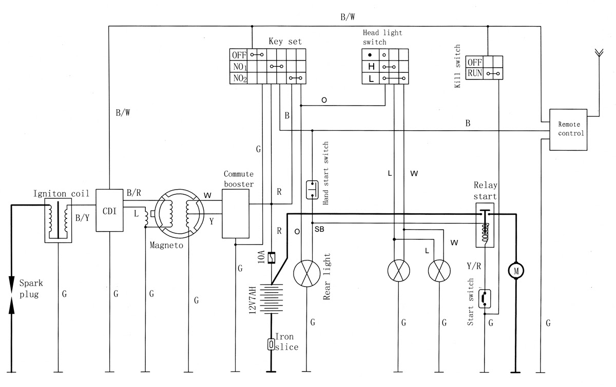
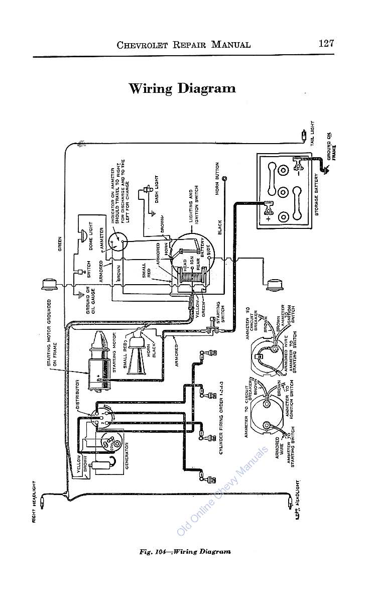
Viper 50 st offroad vehicle pdf manual download. Page 61 127 wiring diagrams the wiring diagram above is for rxl 50 90 the wiring diagram above is for rxl 70 90 and rxl 50m. It shows the components of the circuit as simplified shapes and the knack and signal contacts with the devices. Eton viper 50 wiring diagram wiring diagram is a simplified up to standard pictorial representation of an electrical circuit. There is no test for the cdi module. The rear brake is the primary stopping brake on your vehicle.
Electrical system 121 troubleshooting 125 charging 122 ignition coil 126 electric starter 123 battery caution 127 wiring diagrams 124 battery inspection 128 speedometer and fuel meter 129 wiring diagram 121 troubleshooting. Viper 70 viper 90 viper 90r viper 50m is equipped with rear hydraulic disc brake only the front brakes are controlled by the long brake lever on the right handle bar.
Gallery of Eton Viper 50 Wiring Diagram