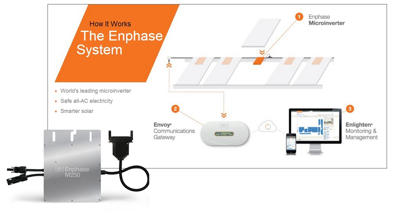
M215 installation and operation enphase microinverter installation installing the enphase microinverter system involves several key steps. If it fails contact enphase customer service to obtain an rma return merchandise authorization number and start the replacement process.
Field Wiring Diagram 240 Vac Single Phase Westbrook
Enphase m215 wiring diagram. Installation and operation manual dec 2016 141 00032 rev 01b enphase m250 and m215 microinverters. M215 field wiring diagram 240 vac review the electrical schematic for the enphase m215 microinverter 240 vac. Risk of equipment damage. Tampering with or opening the enphase microinverter will void the warranty. The wiring connections in the junction box are. A gec grounding electrode conductor is required only for m215 60 2ll.
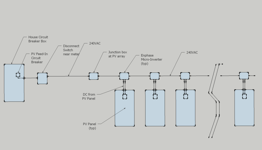
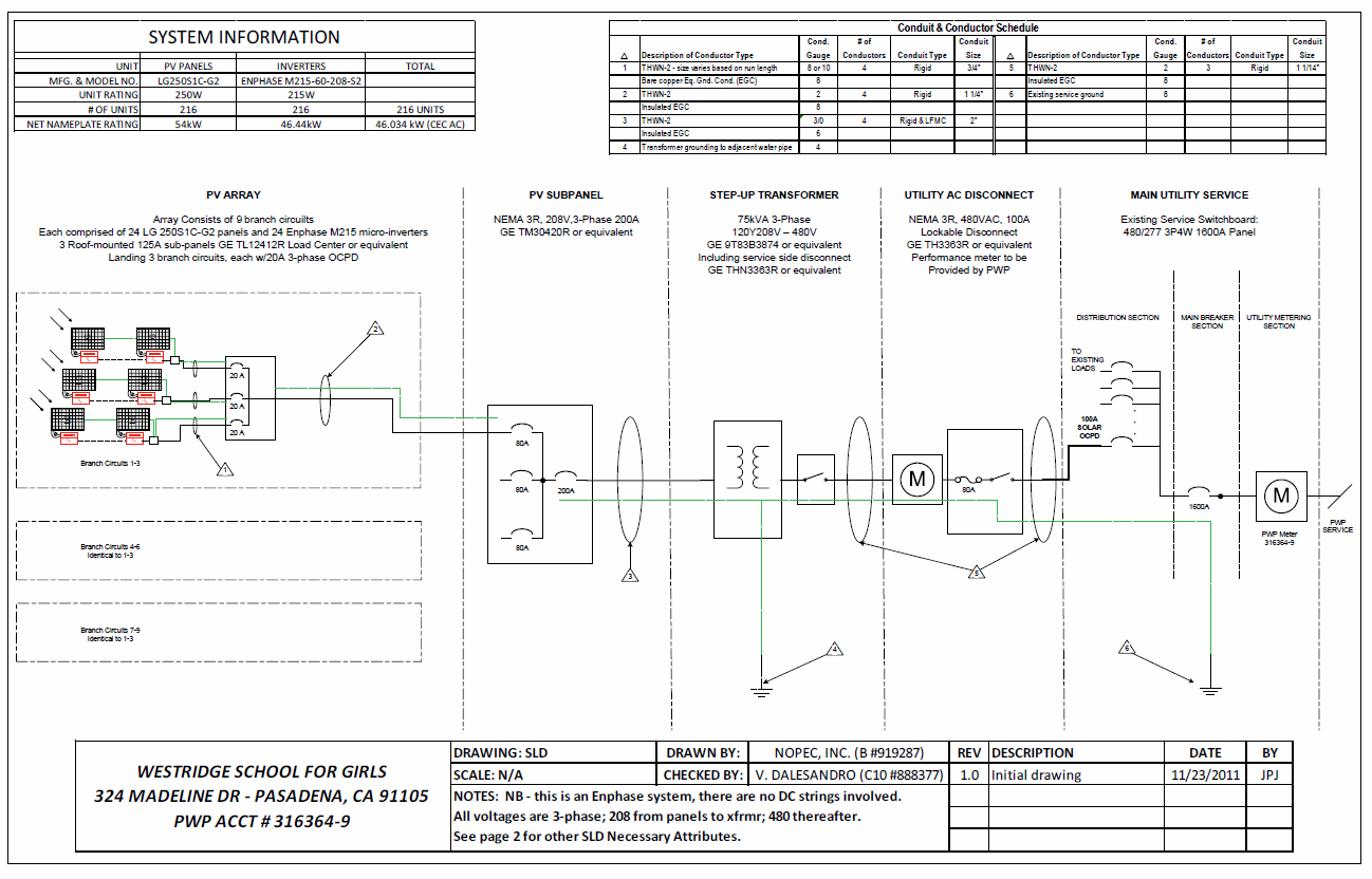
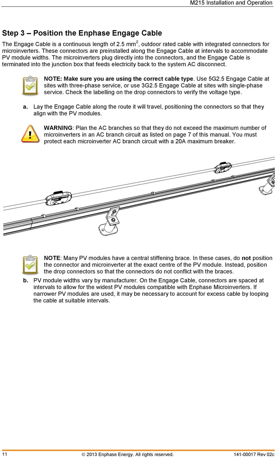
Make sure to measure the line to line and the line to neutral voltage of all service entrance conductors prior to installing any solar equipment. Enphase sells a kit that includes the enphase ac interconnect cable this cable plugs into the first micro inverter and the other end of cable has bare wires to connect to the wiring from the house inside the junction box. The m215 and m250 may be paired only with 60 cell pv. Field wiring diagram 208 vac three phase important. M190 m210 field wiring diagram 240 vac get the electrical schematic for the enphase m190 and m210 240 vac. It reveals the parts of the circuit as simplified forms as well as the power and signal links in between the gadgets.
Sample wiring diagram m215 230 vac single phase 28 sample wiring diagram m215 three phase 29 enphase m215 installation and operation manual 4 pages. Follow the instructions in this section to install enphase m215 microinverters. A wiring diagram is a streamlined standard photographic representation of an electric circuit. The voltages for the 208 vac rated microinverters should be within the following ranges. It contains no user serviceable parts. It is not required for m215 60 2ll ig.
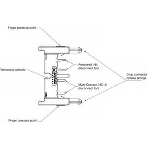
Collection of enphase micro inverter wiring diagram. Line to line 183 to 229 vac line to neutral 106 to 132. You will need one of these. The grounding method shown is one of multiple allowable methods. Each step listed here is detailed in the following pages. Field wiring diagram 240 vac single phase note.
Gallery of Enphase M215 Wiring Diagram