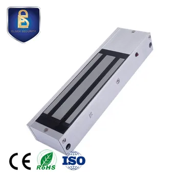
All types of brackets are available to ease installation for both in swing out swing doors. Bolt action lock sp fail safe lk120 12vdc operation operation current 900ma holding current 350ma fail safe type power to lock operation delay time.

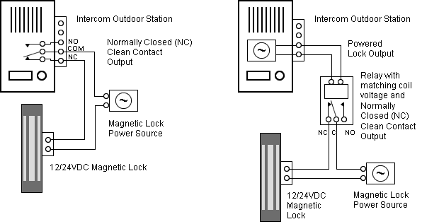
Door Maglock Relay Amp Schematic Sc 1 St Electrical Engineering
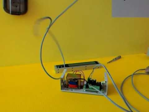
Elock magnetic lock wiring diagram. 0 sec 25 sec 5 sec 9 sec built in delayed egress control point surface mount electric dead bolt lock lk124 1. It has no moving parts thus keeping maintenance to a minimum. Specification 300lbs holding force. The e600 series magnetic lock is mounted to the underside of the header on the stop side of the door. The filler plate will then be removed. Refer to the interconnector manual usually same manual as access control panel since they are often packaged together and note which wires should be connected to.
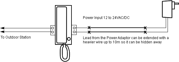
Remove the jumper from the pcb and place only one jumper at the. A wiring diagram is a streamlined conventional pictorial depiction of an electrical circuit. It shows the components of the circuit as simplified shapes and also the power as well as signal connections in between the gadgets. Collection of magnetic door lock wiring diagram. Pinstallation instelectromagnetic locksexcelinst e600vsd rev a3 05 18 page 1 any suggestions or comments to this instruction or. An inswing mounting kit optional can be used when mounting on the hinge side of the door.
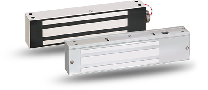
Maglock with filler plate 2. Elock installation manual 2 convert to 24 vdc operation 1. Use ellen key m5 provided in em lock screw set to dismantle inter lock screw at both end. Em lock series elock 300 features elock 300 electromagnetic locks offer cost effective solution with easy installation suitable for variety of application. Insert interconnector wires into magnetic lock. Use ellen key m5 to dismantle bracket screw at both end.
The inside of the access panel includes a diagram with labels. Unscrew the access panel on the magnetic lock using the phillips head screwdriver.
Gallery of Elock Magnetic Lock Wiring Diagram


.png)