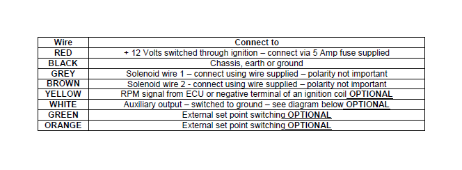
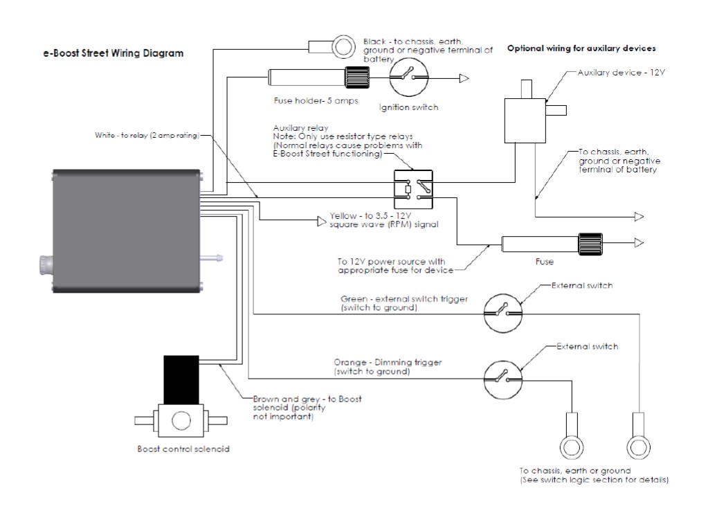
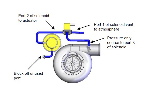
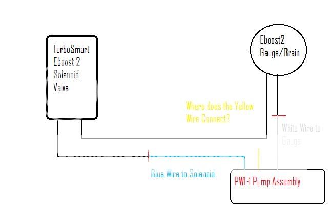
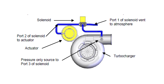
To boost control solenoid. Refer to the following table and diagram for detail on wiring the e boost2.
How To Install A E Boost2 Boost Controller 66mm Black On
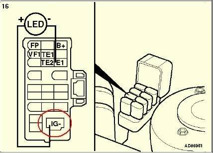
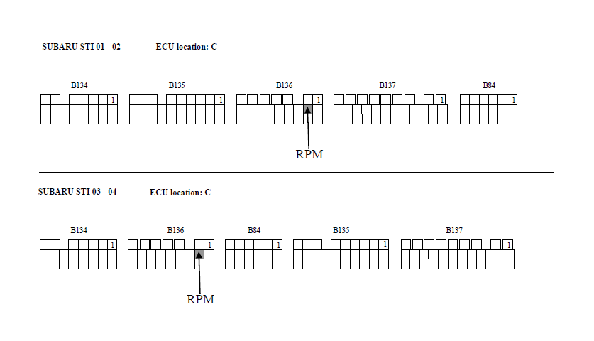
Eboost2 wiring diagram. Basic e boost2 wiring diagram. Wire connect to red 12 volts switched through ignition connect via 5 amp fuse supplied black chassis earth or ground grey solenoid wire 1 connect using wire supplied polarity not important. Refer to the following table and diagram for detail on wiring the e boost2. Refer to the following table and diagram for detail on wiring the e boost2. For vehicle specific ecu wiring diagrams as a guide for the rpm signal that plugs directly into the eboost2 led output with no additional wiring. Refer to the following table and diagram for detail on wiring the e boost2.
Basic e boost2 wiring diagram. Fuse holder 5 amps basic e boost2 wiring diagram yellow wire. Fuse holder 5 amps. Refer to the following table and diagram for detail on wiring the eboost2. Basic e boost2 wiring diagram. Wiring the e boost2 must be connected to a 12 volt negative earth electrical system.
1 wiring loom connect e boost2 to vehicle 1 earth eyelet connect to wiring loom 100 mm heat shrink shield solder joints 2000 mm figure eight wire connect wiring loom to e boost2 solenoid 1 5 amp fuse connect to 12 volts see wiring diagram 10 cable ties secure wiring 1 panel mounting bracket secure e boost2 to panel. All electrical connections must be soldered. Refer to the following table and diagram for detail on wiring the e boost2. Fuse holder 5 amps basic eboost2 wiring diagram 1 before you start important notes. To chassis earth ground or negative terminal of battery brown and grey wires. Fuse holder 5 amps.
Wire connect to red 12 volts switched through ignition connect via 5 amp fuse supplied black chassis earth or ground. To 35 12v squarewave rpm signal from ecu or if using a coil via a tach adapter black wire.
Gallery of Eboost2 Wiring Diagram